Do-it-yourself ring coil for a metal detector. Twisted pair coil for metal detector. After the above procedure, it is necessary to isolate the adhesions using special thermotubes or adhesive tape
You can buy for about 100-300 dollars. The price of metal detectors is strongly interconnected with their detection depth, not every metal detector can "see" coins at a depth of 15 cm. In addition, the presence of a metal type recognizer and interface type also greatly affects the cost of a metal detector, fashionable metal detectors are sometimes equipped with a display for convenient operation .
This article will consider an example of assembling a powerful metal detector called Pirat with your own hands. The device is able to catch coins underground at a depth of 20 cm. As for large objects, it is quite possible to work at a depth of 150 cm.

Video of working with a metal detector:
This metal detector received such a name due to the fact that it is a pulse, this is the designation of its first two letters (PI-impulse). Well, RA-T is consonant with the word radioskot - this is the name of the developers' site, where the homemade product was posted. According to the author, the Pirate is going to be very simple and fast, even basic skills in working with electronics are enough for this.
The disadvantage of such a device is that it does not have a discriminator, that is, it cannot recognize non-ferrous metals. So working with him on areas contaminated with various kinds of metals will not work.
Assembly materials and tools:
- microcircuit KR1006VI1 (or its foreign analogue NE555) - a transmitting node is built on it;
- transistor IRF740;
- K157UD2 microcircuit and VS547 transistor (the receiving unit is assembled on them);
- wire PEV 0.5 (for winding the coil);
- NPN type transistors;
- materials for creating the body and so on;
- electrical tape;
- soldering iron, wires, other tools.
The remaining radio components can be seen in the diagram.


You also need to find a suitable plastic box for mounting the electronic circuit. You will also need a plastic pipe to create a rod on which the coil is attached.
Metal detector assembly process:
Step one. We create printed circuit board
The most difficult part of the device is, of course, the electronics, so it is advisable to start with it. First of all, you need to make a printed circuit board. In total there are several options for boards, depending on the radio elements used. There is a board for NE555, and there is a transistor board. All the necessary files for creating the board are in the article. You can also find other board options on the Internet.
Step two. We install electronic elements on the board
Now the board needs to be soldered, all electronic elements are installed exactly as in the diagram. In the picture on the left you can see the capacitors. These capacitors are film type and have high thermal stability. Thanks to this, the metal detector will work more stably. This is especially true if you use a metal detector in the fall, when it is already quite cold outside.


Step three. Power supply for metal detector
To power the device, you need a source from 9 to 12 V. It is important to note that the device is rather voracious in terms of energy consumption, and this is logical, because it is powerful. One krone battery is not enough for a long time, it is recommended to use 2-3 batteries at once, which are connected in parallel. You can also use one powerful battery (best rechargeable).

Step four. Assembling a coil for a metal detector
Due to the fact that this is a pulse metal detector, the accuracy of the coil assembly is not so important here. Optimum diameter is a mandrel 1900-200 mm, in total you need to wind 25 turns. After the coil is wound, it must be carefully wrapped on top with electrical tape for insulation. To increase the detection depth of the coil, you need to wind it on a mandrel with a diameter of about 260-270 mm, and reduce the number of turns to 21-22. The wire is used with a diameter of 0.5 mm.

After the coil is wound, it must be installed on a rigid body, there should be no metal on it. Here you need to think a little and look for any case that is suitable in size. It is needed in order to protect the coil from shock while working with the device.
The leads from the coil are soldered to stranded wire, about 0.5-0.75 mm in diameter. It is best if these are two wires twisted together.
Step five. Setting up a metal detector
When assembling exactly according to the scheme, it is not necessary to adjust the metal detector, it already has maximum sensitivity. To fine-tune the metal detector, you need to turn the variable resistor R13, you need to achieve rare clicks in the speaker. If this is achieved only in the extreme positions of the resistor, then it is necessary to change the value of the resistor R12. The variable resistor should adjust the device for normal operation in the middle positions.
Making a Good Coil
Usually, metal detector coils are wound in bulk on some kind of mandrel - a saucepan, a can, etc. suitable diameter. Then wrap with electrical tape, shielding foil and again with electrical tape. Such coils do not have the necessary structural rigidity and stability, are very sensitive to the slightest deformation and change the frequency greatly even with simple finger pressure! A metal detector with such a coil will have to be adjusted every now and then, and from the knob-regulator your fingers will constantly be in big sore corns :). It is often recommended to “fill in epoxy” with such a coil, but where should you fill it, epoxy, if the coil is frameless? .. I can offer a simple and easy way production of a high-quality coil, sealed and resistant to all kinds of external influences, having sufficient structural rigidity and, moreover, providing simple attachment to a stick-rod without any brackets.
For the coil frame, you can make it using a plastic box (cable channel) of a suitable section. For example, for 80 - 100 turns of wire with a cross section of 0.3 ... 0.5 mm, a box with a cross section of 15 X 10 or less is quite suitable, depending on the cross section of your particular wire for winding. A single-core copper wire for low-current electrical circuits is suitable as a winding wire; it is sold in coils, such as CQR, KSPV, etc. This is a bare copper wire in PVC insulation. The cable can contain from 2 or more single-core wires with a cross section of 0.3 ... 0.5 mm in insulation different colors. We remove the outer sheath of the cable and get a few necessary wires. Such a wire is convenient in that it excludes the possibility of a short circuit of the turns in case of poor-quality insulation (as in the case of a wire with varnish insulation of PEL or PEV grades, where minor damage to it is not visible to the eye). To determine how long the wire should be to wind the coil, you need to multiply the circumference of the coil by the number of its turns and leave a small margin for the conclusions. If there is no piece of wire of the required length, you can make a winding of several pieces of wire, the ends of which are well soldered to each other and carefully insulated with tape or heat shrink tubing.
We remove the cover from the cable channel and cut the side walls with a sharp knife after 1 ... 2 cm:

After that, the cable channel can easily go around the cylindrical surface of the required diameter (jar, pan, etc.), corresponding to the diameter of the metal detector coil. The ends of the cable channel are glued together and a cylindrical frame with sides is obtained. It is easy to wind the required number of turns of wire on such a frame and coat them, for example, with varnish, epoxy, or fill everything with sealant.

From above, the frame with the wire is closed with a cable channel cover. If the sides of this cover are low (this depends on the size and type of the box), then side cuts on it can be omitted, because it already bends quite well. The output ends of the coil are brought out next to each other.

This results in a sealed coil with good structural rigidity. All sharp edges, protrusions and irregularities in the cable channel should be smoothed out with sandpaper or wrapped with a layer of electrical tape.

After checking the coil for operability (this can be done by connecting the coil even without a screen to your metal detector by the presence of generation), filling it with glue or sealant and machining the irregularities, you should make a screen. To do this, take foil from electrolytic capacitors or food foil from the store, which is cut into strips 1.5 ... 2 cm wide. The foil is wound around the coil tightly, without gaps, overlapping. Between the ends of the foil in the place of the coil leads must be left gap 1 ... 1.5 cm , otherwise a short-circuited coil is formed and the coil will not work. The ends of the foil should be secured with glue. Then, from above, the foil is wrapped along the entire length with any tinned wire (without insulation) in a spiral, in increments of about 1 cm. The wire must be tinned, otherwise incompatible metal contact (aluminum-copper) may occur. One of the ends of this wire will be the common wire of the coil (GND).

Then the whole coil is wrapped with two or three layers of electrical tape to protect the foil screen from mechanical damage.
Tuning the coil to the desired frequency consists in the selection of capacitors, which, together with the coil, form an oscillatory circuit:

The actual inductance of the coil, as a rule, does not correspond to its calculated value, so the desired circuit frequency can be achieved by selecting the appropriate capacitors. To facilitate the selection of these capacitors, it is convenient to make the so-called "capacity store". To do this, you can take a suitable switch, for example, type P2K for 5 ... 10 buttons (or several such switches with fewer buttons), with dependent or independent fixation (anyway, the main thing is to be able to turn on several buttons at the same time). The more buttons on your switch, the correspondingly more containers can be included in the "shop". The scheme is simple and is shown below. The entire installation is hinged, the capacitors are soldered directly to the button terminals.


Here is an example for selecting capacitors series resonant circuit
(two capacitors + coil) with capacitances of about 5600 pF. By switching the buttons, you can use different capacities indicated on the corresponding button. In addition, by turning on several buttons at the same time, you can get the total capacity. For example, if you simultaneously press buttons 3 and 4, we get total capacitances of 5610 pF (5100 + 510), and when you press 3 and 5 - 5950 pF (5100 + 850). Thus, it is possible to create the necessary set of capacitances for the exact selection of the desired loop tuning frequency. You need to choose the capacitor capacities in the "capacitance store" based on the values \u200b\u200bthat are given in your metal detector circuit. In the example given here, the capacitances of the capacitors according to the circuit are 5600pF. Therefore, the first thing included in the "shop" is, of course, these containers. Well, then take containers with lower ratings (4700, 4300, 3900 pF for example), and very small ones (100, 300, 470, 1000 pF) for a more accurate selection. Thus, by simply switching the buttons and their combination, you can get a very wide range of capacitances and tune the coil to the desired frequency. Well, then it remains only to pick up capacitors with a capacitance, equal to that, which you got as a result on the "capacity store". Capacitors with such a capacity should be placed in the working circuit. It should be borne in mind that when selecting containers, the “store” itself must be connected to a metal detector exactly with the wire / cable that will be used in the future, and the wires connecting the “store” to the coil must be made as short as possible! Because all wires also have their own capacitance.

Discuss the article METAL DETECTORS: ABOUT COILS
Clone PI-W and, now, it came to the manufacture of a mono search coil. And since I am currently experiencing some financial difficulties, I faced a difficult task - to make the coil myself from the cheapest possible materials.
Looking ahead, I’ll say right away that I coped with the task. As a result, I got this sensor:
By the way, the resulting coil-ring is perfect not only for Clone, but also for almost any other impulse device (Kashchei, Tracker, Pirate).
I'll go into great detail, because the devil is often in the details. Moreover, there are a dime a dozen short stories of making coils on the Internet (like, we take this, then we cut it off, wrap it, glue it and that's it!) And you start doing it yourself and it turns out that the most important was mentioned in passing, and something was forgotten to be said at all ... And it turns out that everything is more complicated than it seemed at the very beginning.
This will not happen here. Ready? Go!
idea
Easiest for self-manufacturing The following design seemed to me: we take a disk made of sheet material with a thickness of ~ 4-6 mm. The diameter of this disk is determined by the diameter of the future winding (in my case it should be 21 cm).
Then we glue two discs of a slightly larger diameter to this pancake on both sides, so that we get, as it were, a bobbin for winding the wire. Those. such a coil, greatly enlarged in diameter, but flattened in height.
For clarity, I will try to depict this in the drawing: 
I hope the main idea is clear. Just three discs glued together over the entire area.
Material selection
As a material, I planned to take plexiglass. It is perfectly processed and glued with dichloroethane. But, unfortunately, I could not find it for free.
All kinds of collective farm materials such as plywood, cardboard, bucket lids, etc. I immediately discarded as unsuitable. I wanted something strong, durable and preferably waterproof.
And then my eyes turned to fiberglass ...
It's no secret that from fiberglass (or from glass mat, fiberglass) do whatever your heart desires. Even motor boats and car bumpers. The fabric is impregnated with epoxy resin, give it the desired shape and leave until completely cured. It turns out a durable, waterproof, easily recycled material. And this is just what we need.
So, we need to make three pancakes and ears for attaching the bar.
Production of individual parts
Pancakes #1 and #2
Calculations showed that to obtain a sheet with a thickness of 5.5 mm, 18 layers of fiberglass should be taken. To reduce the consumption of epoxy, it is better to cut the fiberglass in advance into circles of the required diameter.
For a disk with a diameter of 21 cm, 100 ml of epoxy was just enough.
Each layer must be thoroughly smeared, and then the entire stack should be put under the press. The more pressure, the better - the excess resin will be squeezed out, the mass of the final product will become a little less, and the strength will be a little more. I loaded about a hundred kilograms from above and left it until the morning. The next day I got this pancake: 
This is the most massive part of the future coil. He weighs - be healthy! 
Then I’ll tell you how, due to this spare part, it will be possible to significantly reduce the weight of the finished sensor.
A disk 23 cm in diameter and 1.5 mm thick was made in exactly the same way. Its mass is 89 g.
Pancake №3
The third disk did not have to be glued. In my possession was a sheet of fiberglass right size and thickness. It was a printed circuit board from some ancient device: 
Unfortunately, the board had metalized holes, so I had to spend some time drilling them.
I decided that this would be the top disk, so I made a hole in it for the cable entry. 
Ears for bar
The rest of the textolite was just enough for the ears to attach the sensor housing to the rod. I sawed out two pieces for each ear (to be strong!) 
In the ears, you must immediately drill holes for the plastic bolt, since then it will be very inconvenient to do this. 
By the way, this is a fixing bolt for the toilet seat.
So, all the components of our coil are ready. It remains to glue it all into one big sandwich. And do not forget to bring the cable inside.
Assembling into one
First, the upper disc of perforated fiberglass was glued together with the middle pancake of 18 layers of fiberglass. It took literally a few milliliters of epoxy - this was enough to coat both surfaces to be glued over the entire area. 


Ear mounting
I cut the grooves with a jigsaw. In one place, of course, I overdid it a little: 
To make the ears fit well, I made a small bevel at the edges of the cuts: 
Now it was necessary to decide which option is better? Ears can be put in different ways ... 
Coils of industrial production are often made according to the right option, but I like the left one more. I tend to make the wrong decisions...
In theory, the right way is better balanced, because the rod mount is closer to the center of gravity. But it is far from a fact that after lightening the coil, its center of gravity will not shift in one direction or another.
The left method of fastening purely visually looks more pleasant (IMHO), besides, in this case, the total length of the folded metal detector will be a couple of centimeters less. For someone who plans to carry the device in a backpack, this may be important.
In general, I made my choice and proceeded to gluing. I generously smeared it with bauxite, securely fixed it in the desired position and left it to harden: 
After hardening, everything sticking out from the back side was sanded with sandpaper: 

Cable entry
Then, using a round file, I prepared grooves for the conductors, led the connecting cable through the hole and glued it tightly: 

To prevent strong kinks, the cable at the entry point had to be somehow strengthened. For these purposes, I used, out of nowhere, taken from me, such a rubber bullshit: 
In short, I planed a little fiberglass: 
and coolly kneaded it with bauxite with the addition of pasta from ballpoint pen. The result was a viscous substance, similar to wet hair. With this composition, you can cover up any cracks without problems: 
Pieces of fiberglass give the putty the necessary viscosity, and after hardening provide increased strength of the glue line.
In order for the mixture to be properly compacted, and the resin soaked the turns of the wire, I wrapped it all with electrical tape in an interference fit: 
Electrical tape must be green or, at worst, blue.
After everything had cooled down, I was wondering how solid the construction turned out. It turned out that the coil can easily withstand my weight (about 80 kg).
In fact, we do not need such a heavy-duty coil, its weight is much more important. Too much mass of the sensor will definitely make itself felt with pain in the shoulder, especially if you plan to conduct a long search.
Lightweighting
To reduce the weight of the coil, it was decided to cut out some sections of the structure: 
This manipulation allowed to throw off 168 grams of excess weight. At the same time, the strength of the sensor practically did not decrease, as can be seen from this video:
Now, in hindsight, I understand how it was possible to make the coil a little easier. To do this, it was necessary to make large holes in the middle pancake in advance (before gluing everything together). Something like this: 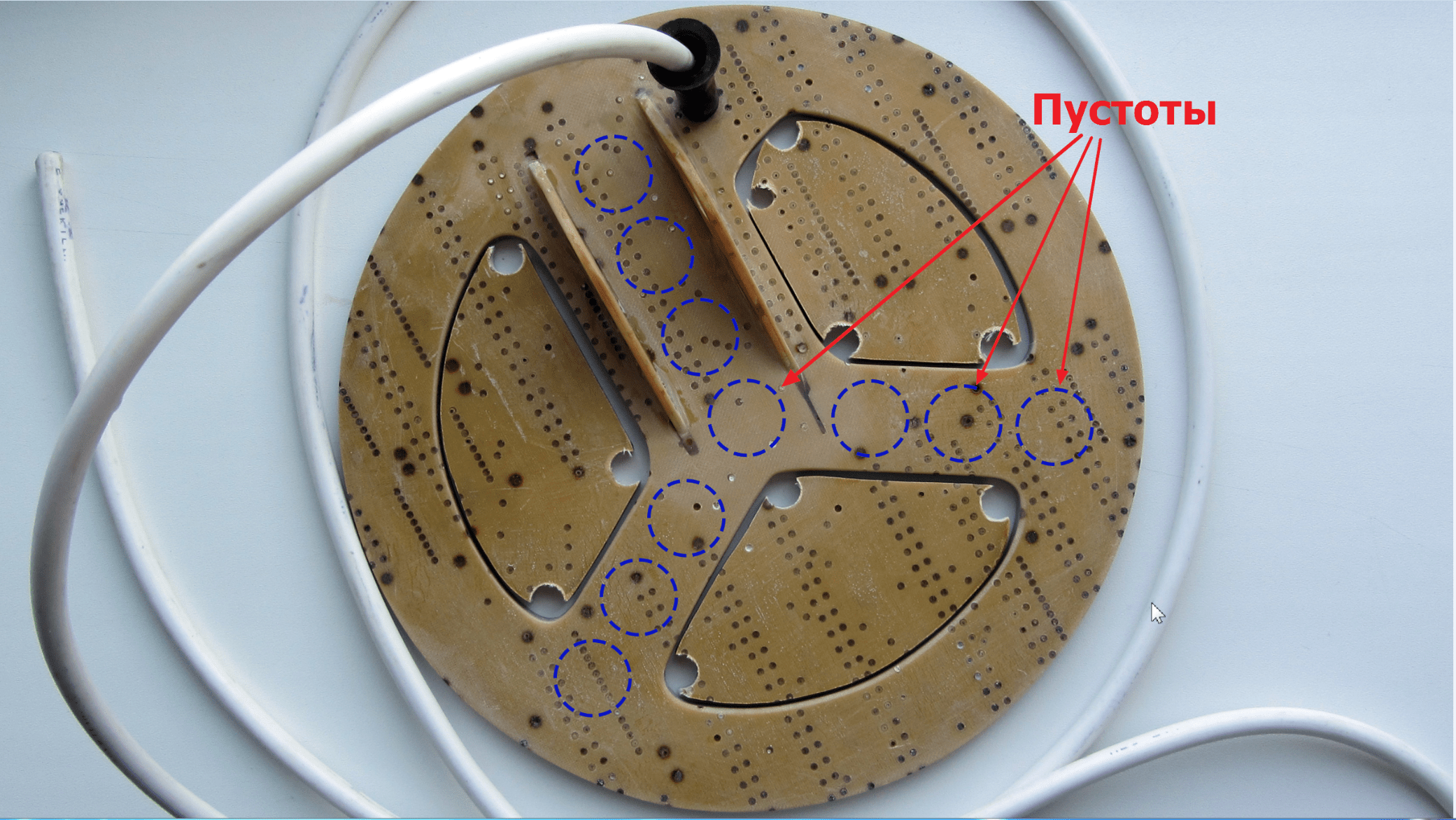
The voids inside the structure would have almost no effect on strength, but they would reduce total weight another 20-30 grams. Now, of course, it's too late to rush about, but I'll keep it in mind for the future.
Another way to simplify the design of the sensor is to reduce the width of the outer ring (where the wire turns are laid) by 6-7 millimeters. Of course, this can be done now, but so far there is no such need.
Finishing color
I found an excellent paint for fiberglass and fiberglass products - epoxy resin with the addition of a dye of the desired color. Since the entire construction of my sensor is based on bauxite, the resin-based paint will have excellent adhesion, and will lay down like a native.
I used PF-115 alkyd enamel as a black dye, adding it until the desired hiding power was obtained.
As practice has shown, a layer of such paint is held very firmly, and it looks as if the product has been dipped in liquid plastic: 

In this case, the color can be any, depending on the enamel used.
The final mass of the search coil together with the cable after painting is 407 g 
The cable separately weighs ~ 80 grams.
Examination
After our homemade coil for the metal detector was completely ready, it was necessary to check it for the absence of an internal break. The easiest way to check is to measure the resistance of the winding with a tester, which should normally be very low (maximum 2.5 ohms).
In my case, the resistance of the coil, together with two meters of the connecting cable, turned out to be around 0.9 ohms.
Unfortunately, in such a simple way it will not be possible to detect an interturn circuit, so you have to rely on your accuracy when winding. A short circuit, if any, will immediately manifest itself after the circuit is started - the metal detector will consume increased current and have an extremely low sensitivity.
Conclusion
So, I think that the task was completed successfully: I managed to make a very strong, water-resistant and not too heavy coil from the most waste materials. List of expenses:
- Fiberglass sheet 27 x 25 cm - free of charge;
- Fiberglass sheet, 2 x 0.7 m - free of charge;
- Epoxy resin, 200 g - 120 rubles;
- Enamel PF-115, black, 0.4 kg - 72 rubles;
- Winding wire PETV-2 0.71 mm, 100 g - 250 rubles;
- Connecting cable PVA 2x1.5 (2 meters) - 46 rubles;
- Cable entry - free of charge.
Now I am faced with the task of manufacturing exactly the same rogue rod. But it's already.

With the onset of spring, more and more often on the banks of the rivers you can meet people with metal detectors. Most of them are engaged in "gold mining" purely out of curiosity and excitement. But a certain percentage really earns a lot of money looking for rare gizmos. The secret of the success of such research is not only in experience, information and intuition, but also in the quality of the equipment with which they are equipped. professional tool is expensive, and if you know the basics of radio mechanics, then you probably have thought more than once about how to make a metal detector with your own hands. The editors of the site will come to your aid and tell you today how to assemble the device yourself using diagrams.
Read in the article:
Metal detector and its device

Such a model costs more than 32,000 rubles, and, of course, such a device will not be affordable for non-professionals. Therefore, we suggest studying the device of a metal detector in order to assemble a variation of such a device yourself. So, the simplest metal detector consists of the following elements.

The principle of operation of such metal detectors is based on the transmission and reception electromagnetic waves. The main elements of a device of this type are two coils: one is a transmitter, and the second is a receiver.

The metal detector works like this: the magnetic lines of force of the primary field (A) of red color pass through the metal object (B) and create a secondary field in it (green lines). This secondary field is picked up by the receiver, and the detector sends sound signal operator. According to the principle of operation of emitters, electronic devices of this type can be divided into:
- Simple, working on the principle of "reception-transmission".
- Induction.
- Pulse.
- Generator.
The cheapest devices are of the first type.

An induction metal detector has one coil that sends and receives a signal at the same time. But devices with pulse induction differ in that they generate a transmitter current that turns on for a while and then turns off abruptly. The coil field generates pulsed eddy currents in the object, which are detected by analyzing the attenuation of the pulse induced in the receiver coil. This cycle repeats continuously, maybe hundreds of thousands of times per second.
How a metal detector works depending on the purpose and technical device
The principle of operation of a metal detector varies depending on the type of device. Let's consider the main ones:
- Dynamic Type Devices. The simplest type of device that scans the field all the time. The main feature of working with such a device is that it is necessary to be in motion all the time, otherwise the signal will disappear. Such devices are easy to use, however, they are weakly sensitive.
- Devices of impulse type. They have great sensitivity. Often, several additional coils go to such a device for tuning under different types soils and metals. Requires certain skills to set up. Among the devices of this class, one can single out electronic devices operating at a low frequency - not higher than 3 kHz.

- Electronic devices, on the one hand, do not give a reaction (or give a weak one) to unwanted signals: wet sand, small pieces of metal, shot, for example, and, on the other hand, provide good sensitivity when searching for hidden water pipes and trails central heating, as well as coins and other metal objects.
- Depth detectors imprisoned for the search for objects located at an impressive depth. They can detect metal objects at a depth of up to 6 meters, while other models “penetrate” only up to 3. For example, the Jeohunter 3D depth detector is capable of searching and detecting voids and metals, while showing objects found in the ground in 3- measured form.

Deep detectors work on two coils, one is parallel to the ground surface, the other is perpendicular.
- Stationary detectors- this is a framework established at especially important protected objects. They calculate any metal objects in the bags and pockets of people passing through the loop.

Which of the metal detectors are suitable for DIY at home
The simplest devices that you can assemble yourself include devices that work on the principle of receiving and transmitting. There are schemes that even a novice radio amateur can do, for this you just need to pick up a certain set of parts.

There are many video tutorials on the internet. detailed explanation how to make a simple do-it-yourself metal detector. Here are the most popular ones:
- Metal detector "Pirate".
- Metal detector - butterfly.
- Emitter without microcircuits (IC).
- A series of metal detectors "Terminator".
However, despite the fact that some entertainers are trying to offer systems for assembling a metal detector from a phone, such designs will not pass the “battle” test. It’s easier to buy a children’s toy metal detector, it will be more sense.

And now more about how to make a simple metal detector with your own hands using the Pirate design as an example.
Homemade metal detector "Pirate": a diagram and a detailed description of the assembly
Homemade products based on the metal detector of the Pirate series are one of the most popular among radio amateurs. Due to the good working qualities of the device, it can “detect” an object at a depth of 200 mm (for small items) and 1500 mm (large items).
Parts for assembling a metal detector
Metal detector "Pirate" is a device of impulse type. To make the device, you will need to purchase:
- Materials for the manufacture of the body, rods (you can use plastic pipe), holder and so on.
- Wires and electrical tape.
- Headphones (suitable from the player).
- Transistors - 3 pieces: BC557, IRF740, BC547.
- Chips: K157UD2 and NE
- Ceramic capacitor - 1 nF.
- 2 film capacitors - 100 nF.
- Electrolytic capacitors: 10 microfarad (16 V) - 2 pieces, 2200 microfarad (16 V) - 1 piece, 1 microfarad (16 V) - 2 pieces, 220 microfarad (16 V) - 1 piece.
- Resistors - 7 pieces per 1; 1.6; 47; 62; 100; 120; 470 kOhm and 6 pieces for 10, 100, 150, 220, 470, 390 Ohm, 2 pieces for 2 Ohm.
- 2 diodes 1N148.
Do-it-yourself metal detector schemes
The classic circuit of the metal detector of the "Pirate" series is built on the NE555 chip. The operation of the device depends on the comparator, one output of which is connected to the IC pulse generator, the second to the coil, and the output to the speaker. In case of detection of metal objects, the signal from the coil goes to the comparator, and then to the speaker, which notifies the operator about the presence of the objects being searched for.

The board can be placed in a simple junction box, which you can buy at an electrician's store. If such a tool is not enough for you, you can try to make a device of a more perfect plan, a scheme for making a metal detector with a reference to gold will help you.

How to assemble a metal detector without using chips
This device uses Soviet-style KT-361 and KT-315 transistors to generate signals (similar radio components can be used).
How to assemble a metal detector circuit board with your own hands
The pulse generator is assembled on the NE555 chip. Through the selection of C1 and 2 and R2 and 3, the frequency is adjusted. The pulses obtained as a result of scanning are transmitted to transistor T1, and it transmits a signal to transistor T2. Amplification of the audio frequency occurs on the transistor BC547 to the collector, and headphones are connected.

To place radio components, a printed circuit is used, which can be easily made independently. To do this, we use a piece of sheet getinax covered with copper electrical foil. We transfer the connecting parts to it, mark the attachment points, drill holes. We cover the tracks with a protective varnish, and after drying we lower the future board into ferric chloride for pickling. This is necessary to remove unprotected sections of copper foil.
How to make a coil for a metal detector with your own hands
For the base, you need a ring with a diameter of about 200 mm (ordinary wooden hoops can be used as the base), on which 0.5 mm wire is wound. To increase the depth of metal detection, the coil frame should be in the range of 260–270 mm, and the number of turns should be 21–22 rpm. If you do not have anything suitable on hand, you can wind the coil on a wooden base.
Coil of copper wire on a wooden base
| Illustration | Action Description |
 | For winding, prepare a board with guides. The distance between them is equal to the diameter of the base on which you will mount the coil. |
 | Wind the wire around the perimeter of the fasteners in 20-30 turns. Fasten the winding with electrical tape in several places. |
 | Remove the winding from the base and give it a rounded shape, if necessary, additionally fasten the winding in a few more places. |
 | Connect the circuit to the device and test its operation. |
Twisted pair coil in 5 minutes
We will need: 1 twisted pair 5 cat 24 AVG (2.5 mm), a knife, a soldering iron, solder and a multitester.
| Illustration | Action Description |
 | Fold the wire into two skeins with a pigtail. Leave 10 cm on each side. |
 | Strip the winding and free the wires for connection. |
 | We connect the wires according to the diagram. |
 | For better fixing, solder them with a soldering iron. |
 | Test the coil in the same order as the copper wire device. The winding leads must be soldered to a stranded wire with a diameter in the range of 0.5–0.7 mm. |
Brief instructions for setting up a do-it-yourself Pirate metal detector
After the main elements of the metal detector are ready, we proceed to assembly. We fix all the nodes on the metal detector rod: a body with a coil, a receiving-transmitting unit and a handle. If you did everything correctly, then additional manipulations with the device will not be required, since it initially has maximum sensitivity. Finer tuning is performed using a variable resistor R13. Normal operation of the detector should be ensured with the middle position of the regulator. If there is an oscilloscope, then with its help at the gate of the transistor T2 it is necessary to measure the frequency, which should be 120–150 Hz, and the pulse duration should be 130–150 μs.
Is it possible to make an underwater metal detector with your own hands
The principle of assembling an underwater metal detector is no different from the usual one, with the only difference being that you have to work on creating an impenetrable shell using a sealant, as well as placing special light indicators that can report a find from underwater. An example of how it will work in the video:
Do-it-yourself metal detector "Terminator 3": detailed diagram and video assembly instructions
For many years, the Terminator 3 metal detector has taken pride of place in the ranks of homemade metal detectors. The two-tone device works on the principle of induction balance.

Its main features are: low power consumption, metal discrimination, non-ferrous metal mode, gold only mode and very good search depth performance compared to semi-professional branded metal detectors. We offer you the most detailed description assembly of such a device from the craftsman Viktor Goncharov.
How to make a do-it-yourself metal detector with metal discrimination
Metal discrimination is the ability of the device to distinguish between the detected material and to classify it. Discrimination is based on the different electrical conductivity of metals. Most simple ways definitions of metal types were implemented in old devices and entry-level devices and had two modes - "all metals" and "non-ferrous". The Discrimination feature allows the operator to respond to a phase shift of a certain amount compared to a set (reference) level. In this case, the device cannot distinguish between non-ferrous metals.

How to make a homemade professional metal detector from improvised means in this video:
Features of deep metal detectors
Metal detectors of this type can detect objects at great depths. A good do-it-yourself metal detector looks to a depth of 6 meters. However, in this case, the size of the find should be solid. Such detectors work best for detecting old shells or debris of a sufficiently large size.

There are two types of deep metal detectors: frame and transceiver on the rod. The first type of device is capable of covering a large area of land for scanning, however, in this case, the efficiency and focus of the search is reduced. The second variant of the detector is a point one, it works directed deep into a small diameter. It must be handled slowly and carefully. If you set a goal - to build such a metal detector, the following video may tell you how to do it.
If you have experience in assembling such a device and its application, tell others about it!
A. Bogomolov, Israel
When designing metal detectors, much attention is paid to the technique of manufacturing the coil and the search head. This largely depends on specifications device and ease of use. The cost of "branded" heads is up to 30% of the cost of the device. Around this there is a whole industry for tailoring covers, protective caps and other useful little things. Leading firms apply advanced developments and know-how in their designs. As a rule, technologies are patented, and it is impossible to repeat them in small-scale and home conditions.
Among improvised designs Tracker-FM and Tracker-PI mallodetectors are popular. This is a joint development of Yu. Kolokolov from Donetsk and A. Shchedrin from Moscow. Modern element base, unpretentiousness in operation, ease of adjustment, repeatability and high technical characteristics of these devices have become available a large number search enthusiasts.
I took the Tracker-FM circuit as a basis. During the manufacturing process, the technology of manufacturing and testing a metal detector operating on the principle of a frequency meter was perfected. Since the parameters of the device are determined by the stable operation of the generator, the properties of which are more dependent on the mechanical strength and quality factor of the circuit, it was decided to place a coil and in the search head. A coil with a diameter of 180 mm has 140 turns of 0.3 mm wire. Operating frequency 17.4 kHz. The search head is made of durable foam, it contains a compartment for placing the generator board. The frequency drift for five minutes after switching on is 50 Hz. In the future, the frequency is "worth it". The device has static, dynamic, "turbo", "reset" and off LED indication modes. The search head is attached to a rod made of plastic fishing rod elements. The bar at an angle of 45 degrees is attached to the handle, which houses the batteries, controller, buttons and control knobs. At the end of the handle are connectors for headphones and a charger. A stabilizer is placed on the bar for the stability of the device in the “lying side by side” mode.
4th house. Seven NiCd batteries with a capacity of 400 mA ensure the instrument's performance for 24 hours in normal mode and 18 hours in turbo mode. The device turned out to be very light, my eight-year-old son can easily work with it.
Coil making
First you need to assemble a device for winding the coil (Fig. 1.1).
As you can see from the figure, the basis is a board with a thickness
Rice. 1.1. Coil winder 1S…20 mm. Sawdust slabs are not suitable for this. The upper surface must be treated with sandpaper. When winding, they will slide along it. fingers and a hand. We take a compass and draw a circle of the required radius. For Tracker-FM it is 90 mm (diameter 180 mm). When crimping and leveling, the coil will slightly reduce its size, and the diameter of the central coil in the cross section will be exactly 180 mm. We divide the circle with a compass or "by eye" into equal parts, so that the distance between adjacent points is 20 ... 2S mm. Let's prepare the nails. Their length should be 45…S0 mm and thickness 2 mm. We drill holes at the marked points to a depth of 10 mm and with a diameter two times smaller than the diameter of the nail bar.
There are two ways of winding: on "insulation" or on "cambric". In the first case, an insulating tape serves as a frame for winding, followed by wrapping the tape around the winding. In the second case, tubes or cambric are put on the nails, which are the frame for winding. Winding on a bare nail is a waste of time and wire (Fig. 1.2). 
Rice. 1.2. Tape for insulation
We will wind the winding on the insulation, the tape should stretch and have the smallest thickness. For experienced craftsmen, I recommend winding on fiberglass. Its width is equal to the circumference of the section of the coil. On the hammered nails with a slight tension, wind the tape with the sticky side out. At the junction of the coil, we glue the joint 10 mm long. We correct and align the tape ring by moving it a little to the nail heads. This is necessary to increase the lower gap when tying the coil. Approximately so, (Fig. 1.2).
We hammer in the central nail, it is needed to hold the beginning and end of the coil. It must be remembered that when manual way winding, the wire is twisted, so it is necessary to install tis]si in the plane of the winding table at a distance of a meter and a half. Clamp the vertical axis in a vise, on which put the reel with the wire. It should rotate with some effort. Between two nails, in the center of the tape, we pierce a hole with an awl and insert a wire with a diameter of 0.3 mm into it, after putting on it a colored cambric. We twist the beginning of the wire around the central nail, bend 10 mm of cambric with the wire in the direction of winding and lay the first turn in the center of the tape to ourselves, thinking that there are still 139 left. The heaviest are the first 20 and the last 20. The first because you need to get used to it, and there is little room for the latter. When winding, the wire should be kept in the center, it will blur itself in the form of a lens along the width of the insulation, but this is not scary, then we will fix it. After winding 50 turns, you need to take a break and prepare the epoxy. At worst, you can use varnish, after checking that it does not dissolve the wire insulation. Epoxy is needed to prepare the floor of a matchbox.
All further operations must be performed with medical gloves and very quickly. We apply a layer of epoxy resin to the coil and continue winding another 50 turns, again a layer of epoxy and the last 40 turns. The rest of the resin is applied to the wound coil. We put a cambric on the cut end of the wire and, passing it through electrical tape, fix it on the central nail. Experience comes with every new reel wound. The number of adhesive layers will increase.

Rice. 1.3. Coil alignment operation
Let's start crimping the coil. To do this, we need a harsh thread of medium thickness. Having tied the end of the thread to the nail, we begin to wrap the coil in a spiral with a step of 2 ... 3 cm per turn. We wrap it together with the insulation, twisting it into a tube around the winding and correcting the bent edges. This is a preliminary wrapping, it is needed for the initial formation of the coil body. As we move, we control the tension of the coil ring by pulling out every fourth nail. It is enough to go through one turn and go to the main bandage. The main bandage is made with a step of 10 ... 15 mm per overlap coil without knitting a knot. Here you need to work hard and pull the coil firmly, giving it the shape of a circle in cross section. As we move, we pull out every second nail and make sure not to tie the coil to the nails. In places of conclusions we make a bandage with a step of 5 mm.
We take out all the nails, take out the coil, inspect it and send it for alignment. We do this operation with balloon or a camera from a soccer ball (Fig. 1.3).
Looking at the figure, it is clear what needs to be done (put on first, and then inflate).
From the moment the glue is prepared to putting the coil on the ball, 15 ... 25 should pass. minutes. During this time, the adhesive retains fluidity and the necessary viscosity to form a circle shape. You can rest, remove the drops of glue on the board and pull out the remaining nails. The board can be used repeatedly and for different diameters by rearranging the nails into the desired holes. The repeatability of the coil parameters is high enough for home conditions.
After an hour, we blow off the ball, and place the coil in a plastic bag or bag. We put it on a flat surface and press it on top with a flat load. This operation is necessary to align the coil in the plane. Leave under load for 24 hours. After a day, we take out the coil, carefully removing it from the bag. In terms of bending and torsion strength, it should resemble a glass ring. With a sharp knife or blade, carefully cut off the protruding ends of the thread and the triple knots that we, in a hurry, imposed.
The winding technology can be improved if the central nail is nailed to the end (to wooden table). In the coil area, install a handle for which you can rotate the entire device. The laying of the coil in this case will be much better.

We pass to the final stage - shielding. To do this, we need a sticky foil. According to the Internet catalog, it is called Aluminum Foil Tare (aluminum foil tape). Foil thickness 30 microns on paper backing. Roll length 45 m, width 50 mm. The roll costs $5. If there is no such “joy” at hand, you will have to look for another foil and glue it with “Moment.” To do this, cover one side of the foil with glue, let it dry
10.. .15 minutes, wrap around the spool as shown in fig. 1.4.
First, tightly wrap the bottom, repeatedly pressing it with your fingers, and then the top, with a slight overlap of 5 mm. We continue to compress the entire coil over the area, until a coil body is uniform in density. At the exit point of the ends, we wind around the coil 5 + 5 = 10 turns of tinned wire, turn to turn. We carefully solder the coils. We wrap the end of the screen wire with a step of 5 mm around the ends of the coil. We check the inductance and windings on the screen. The coil is ready!
Search head manufacturing
Details of the search head are shown in fig. 1.5.
The material for its manufacture is foam. Of all the varieties of foam, you must choose the most durable. It should have a finely porous structure, not crumble when pressed on the edge. Bubbles in the structure of the foam should be no more than 3 ... 5 mm. When cutting with a knife, a flat and smooth surface should remain.
As lathe We use a drill with adjustable speed. We take a workpiece 25 mm thick, draw a circle with a diameter of 200 mm. Using a thin and sharp knife, cut out a circle. This is our pig. We cut out two washers with a diameter of 100 mm from plywood. In the center of the washers and blanks, we drill a hole for the bolt
eight.. . 10 mm. We collect the entire workpiece, tighten it with a nut and clamp it in

Rice. 1.5. Search head details

Rice. 1.6. A fundamental search head with a generator, with a "turbo" mode and turning off the light indication of the drill cartridge. As a cutter, you can use a knife, file, sandpaper wrapped around wooden block or a broken hacksaw. Slowly increase the speed, center and select the best clamping point. We increase the speed and process the workpiece according to the dimensions of the drawing.
We cut the washer with a thin knife at lower speeds and make a groove for the coil and the rod mount.
We make the rod attachment point from 5 mm plywood. It consists of a support disk and two cheeks with holes for attaching the rod. A plastic bolt with a nut for attaching the rod must be taken from the children's designer. .In the disk we make through grooves for attaching the cheeks. We glue all the parts with epoxy. To install the rod mount in the head body, cut a rectangular hole.
To increase the stability of the device, it is necessary to move it to the search head on ΝΕ555. Let's add more options "turbo mode" and turn off the light indication. with additions looks like this (Fig. 1.6).
The purpose of the switches:
51 - turning on the device;
52 - mode On - static, Off - dynamic;
53 - device reset;
54 - Norm - Turbo mode;
55 - indication.
(Fig. 1.7) is made of double-foiled fiberglass and has dimensions of 20 χ 30 mm. The underside tracks are grey.

Rice. 1.7. : a - black and red lines - upper side; b - gray lines - bottom
To install the generator in the search head, we cut out a rectangular hole 25 x 35 mm with a thin knife. The resulting bar is cut along, the bottom thickness is 5 ... 8 mm. We drill a stroke from the coil groove to the generator well. We install the coil in the groove and bring its ends into the well. Before the next operation, I recommend checking and adjusting all the details with great care, since after gluing the coil, the structure becomes
novitsya monolithic and nothing can be changed. We fill the coil with epoxy resin, press it with a washer and place the entire structure under the press for 24 hours. Next, glue the rod attachment point and the bottom of the generator well. We install and solder the ends of the coil to the generator board. Solder the output of the generator to the stereo headphone jack. We fasten the connector to the plexiglass plate, which we glue on top of the well.
We process the surface of the search head with sandpaper and cover it with three layers of white oil paint.
The weight of the finished head is 146 grams. Using this technology, it is possible to manufacture various and more complex heads for all types of small detectors. The photo shows search heads for Tracker-FM (Fig. 1.8) and Tracker-PI (Fig. 1.9).

Rice. 1.8. Photo of the device with a military head Tracker-FM

Rice. 1.9. Photo of a device with a Tracker-PI search head

Rice. 1.10. Appearance Tracker-FM in action
Appearance of Tracker-FM in operation (Fig. 1.10). The button on the handle is the "device reset".
You can find detailed information on how to purchase flashed controllers, assembly kits or ready-made Tracker models on Yuri Kolokolov's website http://home.skif.net/~yukol/russian.htm.
Good luck in designing and interesting finds!