Protective grounding: how to properly build and connect a reliable protective circuit. Do-it-yourself ground loop in a private house: diagram, calculation, installation How to install grounding in a private house
Ensure the safety of those living in the house from damage electric shock necessary - this fact is not disputed. But some circuit breakers or RCD is not enough. It is more reliable in this case to do 220 V grounding in a private house with your own hands. Such a system will allow you not to worry about the lives of those living in the event of an emergency. But it is not easy to fulfill it, although it is quite possible even without special education. Today we will analyze in detail why grounding is required, what is required for installation. It makes sense to consider step by step all the stages of such work.
Why you need grounding should be known not only by a professional electrician, but also by every home master. In simple terms, this is a means of protection against electric shock in the event of an insulation breakdown and the appearance of voltage on the cases and. If it is done in accordance with all the rules, then in the event of an emergency, the electric current will “leave” into the ground, eliminating the possibility of a person getting energized. If the device is installed protective shutdown(RCD), then it will work with such a leak.
Important! Grounding for private houses is calculated in a certain way and has its own parameters that cannot be ignored. If the resistance of the circuit or bus is higher than it should be, there can be no question of any protection.

Electric current can be figuratively compared with water, which flows along the path of least resistance, which means that when this parameter of the grounding bus increases, the discharge will go into the ground through a person.
Grounding in the country is just as important as in a private house, but in this case, only individual ones can be grounded.
Grounding and zeroing: what is the difference between them
They call a protection scheme in which a dead-earthed neutral acts as a neutral conductor. In the event of a breakdown of the insulation, contact of the instrument case with the current-carrying part, a short circuit occurs, causing the protective automation to operate. In private sectors, zeroing is prohibited for safety reasons. It is used only in old-built apartment buildings that do not have a separate ground loop.

Installation in a private house of grounding and lightning protection is especially important if the building is located on a hill or away from high structures. They may have a common outline. In this case, lightning protection works like grounding.
Related article:
In this publication, we will take a closer look at what the terms between them mean, the principle of operation, the advantages and disadvantages of each, when it is possible to use one or another method of protection and electrical safety requirements.
Do-it-yourself grounding schemes for private houses: 380 V and 220 V
There is no significant difference between the scheme of a private house for 3 phases (380 volts) and single-phase (220 volts). But in the cabling it is present. Let's figure out what it is.

With a single-phase network, a three-core cable (phase, zero and earth) is used to power electrical appliances. A three-phase network requires a five-wire electrical wire (the same ground and zero, but three phases). Particular attention should be paid to the disconnection - grounding should not come into contact with zero.
Consider the situation. From the substation comes 4 wires (zero and 3 phases), brought into the switchboard. Having arranged the correct grounding on the site, we put it in the shield and “plant” it on a separate bus. Phase and zero cores pass through all automation (RCD), after which they go to electrical appliances. From the ground bus, the conductor goes directly to the equipment. If the zero contact is grounded, the residual current devices will work for no reason, and such wiring in the house is completely useless.
The do-it-yourself grounding scheme in the country house is simple, but it requires a careful and accurate approach when performing. It is easy to perform it only for one or another electrical appliance. Below we will definitely dwell on this.

Helpful information! Before starting work, you need to draw up a detailed grounding project in a private house. The ground loop diagram is useful during operation and will help in case of an emergency later.
What is a ground loop in a private house: definition and device
A ground loop is a structure of pins and tires located in the ground, providing current removal if necessary. However, not any soil is suitable for a grounding device. Peat, loam or clay soil is considered successful for this, but stone or rock is not suitable.
Very important! The ground loop must pass below the freezing level of the soil. Otherwise, in winter it will not properly perform its functions.

The ground loop is located at a distance of 1 ÷ 10 m from the building. For this, a trench is dug, ending in a triangle. Optimal sizes are the lengths of the sides 3 m. At the corners of an equilateral triangle, electrode pins are driven in, connected by a steel tire or a corner by welding. From the top of the triangle, the tire goes to the house. We will consider in detail the algorithm of actions in step by step instructions below.
Having figured out what the ground loop is, you can proceed to the calculations of the material and dimensions.
Calculation of grounding for a private house: formulas and examples
The rules for the installation of electrical installations (PUE) and GOST set the exact framework for how many ohms should be grounded. For 220 V - this is 8 ohms, for 380 - 4 ohms. But do not forget that for the overall result, the resistance of the soil in which the ground loop is arranged is also taken into account. This information can be found in the table.
| Soil type | Maximum resistance, Ohm | Minimum resistance, Ohm |
| Alumina | 65 | 55 |
| Humus | 55 | 45 |
| Forest deposits | 25 | 15 |
| Sandstone, groundwater depth deeper than 5 m | 1000 | - |
| Sandstone, ground water no deeper than 5 m | 500 | - |
| Sandy-clay soil | 160 | 140 |
| Loam | 65 | 55 |
| peat bog | 25 | 15 |
| Chernozem | 55 | 45 |
Knowing the data, you can use the formula:
- R o – rod resistance, Ohm;
- L is the length of the electrode, m;
- d is the electrode diameter, m;
- T is the distance from the middle of the electrode to the surface, m;
- R eq – soil resistance, Ohm;
- T is the distance from the top of the rod to the surface, m;
- l n – distance between pins, m.
But this formula is difficult to use. For simplicity, we suggest using an online calculator, in which you only need to enter data in the appropriate fields and click the calculate button. This will eliminate the possibility of errors in the calculations.
To calculate the number of pins, we use the formula

where R n - normalized resistance for the grounding device, and ψ is the climatic coefficient of soil resistance. In Russia, they take 1.7 for it.
Consider an example of grounding for a private house, standing on black soil. If the contour is made from steel pipe, 160 cm long and 32 cm in diameter. Substituting the data into the formula, we get n o \u003d 25.63 x 1.7 / 4 \u003d 10.89 . Rounding the result up, we get the required number of ground electrodes - 11.
How to make grounding in a private house
Before you properly make grounding, you should familiarize yourself with the rules and regulations for installation. What matters is the depth of laying the contour, the material, the quality of the connections. It is better to use copper, but its cost is high. Therefore, steel is often used.
The requirements for the ground loop of a private house are as follows:
- Vertical bars not shorter than 16 mm;
- Horizontal - from 10 mm;
- Steel thickness not less than 4 mm;
- steel pipe diameter - not less than 32 mm.
Good to know! It is allowed to use natural grounding conductors - metal structures located underground or pipes (with the exception of pipelines for fuel and lubricants and sewerage). The natural ground electrode must not be coated with anti-corrosion compounds.
All connections are made by welding - bolt ties are not allowed. They quickly oxidize and after six months there will be no sense from the ground loop. It can be made in the form of a triangle next to the dwelling or as a square around the perimeter of the building.
How to make 220 V grounding in a private house with your own hands
| Illustration | Action to take |
 | The device of the ground loop of a private house with their own hands begins with a trench for the future loop. Optimal length side of the triangle is 3 m, but many do not pay attention to it. After the circuit is complete, it will be possible to add pins if the resistance does not suit us. |
 | At the corners of the triangle, about half a meter deep, we drill wells. They will not work deep, but they will help a little to hammer the electrodes into the ground. |
 | For wells, you can use a manual or gasoline hole drill. |
 | In our case, a steel corner is used as a pin, which must first be sharpened. This is easy to do with cutting disc for metal. |
 | Now you need to lower the electrode into the well and hammer into the ground what did not go in. |
 | From the three-meter corner, we only have 15 ÷ 20 cm left. We fill the well with alumina and you can proceed to installing tires. |
 | Tires are attached to the electrodes only by welding. Bolted connections will not work - they do not give the desired density. |
 | Having finished welding the tires to the pins, paint over the connecting seams. The circuit itself cannot be painted, but the welds are subject to corrosion, which can render the entire grounding device unusable in a couple of years. |
 | Next, a ground bus is welded to the house. The length is determined by the distance to the building plus the height. |
 | We fasten it to the foundation with simple dowel-nails with aluminum plugs. |
 | Having drilled two holes in the upper part, we tightly fasten the bolts to which the ground cable going to the house is fixed. |
 | The last step is to paint the part of the tire that is above the ground. Bolts are closed. Because they are stretched, it will not be necessary to twist them, and the paint will protect from external weather phenomena. Installation of the ground loop is completed. |
It becomes clear that it is possible, although not easy, to make a ground loop for a private house with your own hands.
What is a natural ground electrode and how to use it
Consider how to make grounding in the country with your own hands without digging trenches and laying the contour. To do this, you can use natural grounding, which are pipes or metal structures underground.

Very important! Fuel and lubricant pipelines and sewerage cannot be used as a natural grounding conductor. Metal structures should not be painted with paint or coated with anti-corrosion compounds.
Considering the grounding of 380 V of a private house with our own hands, we note that there are no differences in the installation of circuits, as mentioned earlier.
Grounding of individual household appliances and equipment
It often happens that the owners of private houses (especially country houses) do not see the point of installing a full-fledged grounding. We cannot justify or condemn anyone, which means that this option is also worth considering. We will figure out how to ground in a private house without installing the entire protection system.

This is quite simple to do using a natural ground electrode. From it you need to lay the cable directly to the device or to, from which the device is powered. Often, in this way, grounding is performed in a private house, but any other household appliance can be protected in this way.
There are "electricians" who, when asked how to ground an outlet in a private house, advise throwing a jumper from the zero contact to the ground. It is clearly not worth listening to such advice - this is fraught with problems. We will definitely talk about such errors today. And now it is worth dwelling in more detail on how to check the finished ground loop, whether it meets the necessary requirements.

Checking the performance of the grounding device with improvised means
Many do not understand how to check the grounding in a private house without purchasing expensive equipment. To test the completed circuit, you will need a conventional multimeter. After the complete installation of the “ground”, we turn on the power supply and transfer the multimeter handle to the maximum voltage in AC mode. Having measured the voltage between the contacts "phase-zero" and "phase-earth", you need to pay attention to the difference in readings. If it is less than 10 V, this means that the work has been done correctly and the circuit is functioning as it should. If the difference is large, there is a way to improve performance.
From any of the corners of the triangle, a trench is dug, 3 m long. Another electrode is driven in from the edge, which is connected to the main circuit by a bus, in the same way as described in the step-by-step instructions. The trench is backfilled and the check is made again. Usually one additional beam is enough to correct the situation.

Important! The ground loop must be checked once a year. This will protect residents from electric shock in the event of an emergency.
Common mistakes when installing a grounding device
Most common mistake is bypassing the neutral with grounding buses. This leads to unauthorized operation of the residual current devices. It is also dangerous to connect the ground contact to zero in the outlet. In addition to deceptive calmness, this will not give anything. Let's analyze the situation in which zero starts to burn in the shield or junction box. An insulation breakdown occurs on the housing of the household appliance and zero burns out. If he was completely weak, the automation would not have time to work. As a result, we get the loss of zero in the presence of voltage on the case. The result will be disappointing.
Next, we note the connection of the ground wire to or a water riser. You can't do this. The use of a natural grounding conductor is allowed when connected to it in front of the input shield and properly disconnected.
It is not allowed to install protection with an aluminum cable, which has an increased resistance in comparison with copper.
Very important! Work related to electrical installation requires stress relief. A short-term supply of electricity is allowed to check the electrical wire or other parameters, but only if all precautions are observed and electrical safety rules are observed.

Do-it-yourself lightning rod device for a private house
The lightning protection device of a private house is important if the building rises above other buildings in the sector, erected on the outskirts or on a hill. But the zealous owner of even a low dwelling will not neglect him. After all, natural phenomena are difficult to predict, which means you need to be prepared for anything. There are nuances in the implementation of such protection, which we will now consider.

According to the rules and regulations, a lightning rod is installed 0.5÷1.5 m above the highest point in the yard (you should also pay attention to trees). The lightning rod can be made of copper, aluminum or steel. From it, a down conductor without insulation is laid along the roof, which is connected to the protective circuit along the shortest path.
The protective contour is made in the form of a triangle or a straight line. Underground, it is connected to the ground loop of the residential premises - this is a prerequisite.
If the walls are made of , the distance between the down conductor and the surface must exceed 100 mm.
How to calculate the length of the lightning rod
To do this, we use the formula:
h = (r x + 1.63h x ) / 1.5 , where
- h - the required height of the lightning rod;
- r x - the radius of the zone on the roof of the house, protected from lightning;
- h x - the height of the house itself, excluding the lightning rod.

Ready-made grounding kits for a private house: where and at what cost to buy
Despite the fact that self-purchase and installation of a ground loop is cheaper, home craftsmen are increasingly purchasing ready-made grounding kits for a summer residence or a private house. Their installation is easier and therefore faster. However, buying grounding for a private house, the price of which is higher than the material from which it is made, is not acceptable to everyone. Let's try to summarize the average prices for such kits in Russia as of January 2018.
For the purpose of safety, the owners prefer to make grounding in a private house at the design stage of the building. This method of protection will avoid negative consequences as a result of a sharp power surge in electrical network at 220 volts. The article will discuss how to make grounding in a private house, its types, installation sequence and recommendations for work.
In order to make grounding in a private house with your own hands, you need to decide what type of protective circuit you need to install in a particular case. The ground loop has two types: working and protective.
The working type of grounding allows you to ensure reliable and proper operation of powerful industrial equipment. It is not advisable to use it at home, since usually there is no such equipment in residential premises. More often, working ground electrodes are made for an electrical network with a voltage of 380 volts.
With sudden surges in voltage, breakdown of most electrical appliances and equipment is prevented. Typically, such jumps appear when there is significant damage to the insulation in the transformer winding. Also, when a lightning strikes a house, all the charge that falls on the lightning rod will go into the ground, and all home electrical equipment will continue to work stably.
The protective type of grounding is based on the fact that electrical equipment, which is under the influence of alternating current, is purposefully connected to the "ground". This method is recognized as the most effective and most common. If a three-core cable is laid in the house, then there will be no problems with the installation of grounding.

Grounding construction scheme
The last, protective ground loop, has many different installation schemes. Often it is applied to an electrical network with a voltage of 220V. If the installation and installation is done correctly, effective protection of the house from excessive voltage for a long time will be provided. To do this, it is enough to make a “ground” connection in the outlet, and a reliable low-resistance design that is placed underground.
There is a separate list household appliances and appliances that are strongly recommended to be grounded in any of these ways: boiler, computer system unit, microwave oven, washing machine and electric oven.
Ground loop and lightning rod
The ground loop is a three-core cable wire that connects electrical appliances to the ground. With this connection, most of the negative processes in technology (open phases or short circuits), which create a stray current, will be directed to the grounding structure, and then to the ground. The ground loop circuit is quite simple, and you can do it yourself if you follow certain rules.

The protective ground loop scheme provides for the connection to each outlet of the "earth" wire, which will stretch to the grounding structure. When connecting household appliances or electrical equipment to the network, they will also be connected to the ground terminal. All wires must go to the switchboard, and a separate cable will be drawn from it. On the one hand, ground wires from a residential building or premises will be connected to it, and on the other, a grounding structure that will go to a certain depth into the ground.
A lightning rod can also be connected to the ground loop. The lightning rod will allow you to receive a powerful lightning charge and transfer it through the down conductor to the ground. If grounding elements are already made in the house, then additional installation protective device from lightning will be easier. An effective device for receiving a lightning charge must necessarily consist of the following set: lightning rod, down conductor and grounding structure.

If a protective circuit was not installed in the house before, then all these elements must be installed. But when the down conductor and the element connecting the entire home network to the ground are already ready, it is enough to install only a lightning rod. This device is placed well above the highest point of the house to take the hit. You can make such a protective system with your own hands. It does not matter how the lightning rod will look externally, but its core must be hollow. This is necessary so that a conductor is placed in it to connect to the ground loop.
Also, a lightning rod can be made on the site in the form of a separate tower. Its spire will rise 2-3 meters above the maximum point of a residential building, providing reliable protection against lightning strikes. In this case, the grounding protective circuit can be both joint and separate (more costly).
Video “Installation of grounding”
Stages of grounding installation
If you want to make grounding at home yourself, first of all you need to acquire some knowledge from the field of electrical engineering. Also, experts strongly recommend using ready-made grounding installation schemes. It is advisable to familiarize yourself with the rules for the installation of electrical installations (PUE) before starting work.
Then for work it is necessary to have a grounding structure, which will be placed underground. You can purchase a ready-made reliable and certified kit. For example, there is a kit EZ 15, EZ 38 or EZ 48 (the marking determines which kit is needed for the corresponding type of soil). If desired, you can make a similar design yourself, using a similar scheme.
Then you need to determine on which system the ground loop will be arranged in a residential building. The most common system is TT. The marking of the TT system means that the neutral is solidly grounded, and its open conductors are grounded, regardless of the relation to the "ground" of the neutral of the power supply or other points of the supply network. The TT system is characterized by the presence of grounding at the exit to the premises of the house.

You can make grounding using the TT system with your own hands, if you correctly follow its scheme. The TT system is common in the villages, it connects small houses and buildings, change houses and sheds. Typically, the TT system is used when powering the electrical installation up to 1000 volts, and if it is not possible to comply with the conditions of the TN system. For CTs, a residual current device must be connected. One of the main disadvantages of the TT system is the simultaneous failure of the RCD and phase breakdown on the case of a grounded electrical device.
Next, you need the right tool for the job. Kit required wrenches, portable welding machine, grinder, heavy sledgehammer, bayonet shovel, a set of screwdrivers. Using a tool, you need to make a grounding structure. You can stop at the option with the shape of a triangle.
At a sufficient distance from the house, you can draw an equilateral triangle with a distance between the vertices of 1.5 meters. At this point, dig a hole up to a depth of 1 meter. In places of vertices, steel reinforcement is clogged with round section 2-3 meters long and at least 35 mm thick. Then the upper parts of the reinforcement must be connected metal bus 4 cm wide and 4 mm thick.

To do this, you need to cut a set of blanks 1.6-1.7 meters long (with a margin). At correct installation electrodes of the length of the tires are enough to connect them together. When fastening, welding is used. The connecting wire, which will be connected to the ground wires near the switchboard, should preferably be selected with a copper section. Then the trench is buried.
Then you can start connecting all the outlets in the house to the "ground", which is located in the three-core power cable. You need to work with de-energized wiring. When you are convinced that you have made the connection correctly, you can proceed to the control check.
What is prohibited by law

It is very important that during the installation of grounding, the connection technology and the rules for placing electrical installations are observed. If you need to install grounding with your own hands in a house that has a power grid with a voltage of 220 volts, it is quite simple. To do this, you must follow the existing PUE standards. The rules for the installation of electrical installations provide that when installing the circuit, it is impossible to connect or twist the stripped wire contacts from the outside. If there is direct access to such contacts, there may be negative consequences. At high voltages in the network, this zone can pose a serious threat to human life.
It is forbidden to use in the grounding structure the main elements that are covered with paint or other coatings (except for the layer of oxidized metal), including an oxide film. Do not ground electrical household appliances to gas and heating pipes, as well as to water supply. It is forbidden to make a serial connection during installation. The norms of the PUE also provide that they cannot be used as grounding loops reinforced concrete structures with live metal parts. It is also forbidden to use pipes for various purposes with combustible and flammable substances.
Control check
To make sure that the ground loop is done correctly, you need to measure the resistance value at a distance of 12-15 meters. Be sure to correctly distribute the polarity between the contacts connected to the ground electrode ("-") and the set of measuring electrodes ("+"). The distance between the electrodes is 1.5 m. If the resistance value is less than 4 ohms, then everything is done correctly. If the resistance is higher, then you need to find and fix the problem.
Video “We make grounding in the house ourselves”
This video material contains a visual aid that will allow you to independently perform such an operation as organizing grounding. The kit also includes a guide to the construction of the circuit.
5752 Views
According to the electrical standards of the last century, the construction of protective grounding in private property was considered an optional matter. The load was small, steel pipelines coped tolerably with the tasks of diverting electrical leaks. Time runs. Steel and cast iron communications replaced plastic and composites. Country property was filled with numerous household appliances. Water and heat are supplied by powerful pumps, heating devices are working. It's time to protect yourself and the units from the vagaries of a useful, but wayward electric current. Let's do grounding with our own hands! The work is not difficult, the skilled owner will not have problems with the implementation.
The task and device of protective earthing
The purpose of grounding is to divert electrical current that has found a loophole in the insulation to reach the surface. This surface is metal cases and fasteners. washing machines, computers, microwave ovens, electric heating equipment. According to their functional duties, they should not conduct current, but they are always ready to substitute their metal “barrel” for leakage and short circuit current. This warm welcome is often felt by the owners of leaky or overly loaded equipment in the form of light blows, pinches and tingling.

Breakdowns on the body of household units rarely cause serious concern. Well, it shied away a little: it kind of cheered up. However, the apparent absence of serious risks is no reason to relax. The stray currents that have escaped to the outside contribute to discomfort and an unreasonable feeling of anxiety. In addition, ungrounded equipment makes noise, interference occurs in it, which reduces the speed and quality of receiving, processing and transmitting a signal. Such troubles will not disable the equipment instantly, but will significantly help to reduce its working life.

So, a ground loop is needed:
- to protect the owners from electromagnetic radiation, negative mood and ailments;
- to eliminate interference in the electrical network;
- to maintain the performance of the equipment.
Protective grounding will eliminate the above problems by providing the most attractive paths for the current to exit. By the principle of movement, electricity is very similar to water. It flows where there are no barriers, where there is less resistance and where it is easier for it to pass. Those. in order for people and units not to suffer, it is trivial to lay an unobstructed path “to the left” for the electric current, in the case of grounding, by definition, into the ground.
The resistance of the constructed path must be less than that of a person and equipment connected to protective grounding. That's when most of the electricity that has broken through will flow along the intended path with the smallest barriers, go beyond the building and dissipate in the ground. And the owner and equipment will get only the normative minimum.

The grounding system is a closed or linear circuit, which includes:
- two or more metal ground rods, strictly vertically immersed in the ground;
- a horizontal grounding conductor that combines the electrode rods into a common circuit;
- a bus that provides entry to the house and grounding connection to protected units.
An autonomous building may have several grounding systems, but one of them must be connected to the main grounding bus or to the main element - to the switchboard with the formation of a metal connection between the shield and the grounding conductor brought to it.
The choice of geometric shape for the earthing system
The most common configuration, according to which it is easiest to implement the installation of a protective earth loop with my own hands- equilateral triangle. The contour triangular in plan is formed by three metal rods driven into the ground with a sledgehammer, the distance between a pair of which should be equal. In addition to triangles, grounding systems are constructed in the form of squares, straight or rounded lines, or other geometric shapes. Compliance with equal distances between ground electrodes is a mandatory condition, a clear geometry is desirable, but not essential.

Often, autonomous buildings filled with all kinds of equipment are simply surrounded by a ground loop. An excellent, effective option, if there are funds for this and enough free space on the site. More precisely, there is no need for special money for an independent organization of grounding, but the choice of the shape of the contour is most often dictated by the site planned for the grounding device. However, one should not forget that when earthing switches are connected in parallel in one row, the efficiency of the system will be reduced due to the influence of the electrodes on each other. Closed loops are preferred.
There are three or more grounding electrodes in the protective earthing complex. A working ground, created to optimize the signal supplied to the instruments, can have two ground rods. Because the ground is a non-linear conductor, there must be at least two ground electrodes. So it is necessary that a potential surface is formed in the space between them, contributing to the spreading of the current. A single rod is not enough for this.

The working potential of a grounding system is affected by the distance between the vertical electrodes. The more often they are installed, the more effective the grounding. Recommended distance minimum 1.0m, maximum 2.0m. With an increase in the maximum limit between the metal rods, a gap in the potential surface is formed, it will nullify all the arrangement efforts.

The distance between the extreme grounding point and the foundation must be more than 1.0 m. The system will work flawlessly at a distance of 4-6m from home. It is pointless to arrange grounding further than 10m from the building.
Details about the components of the contour
It was mentioned above that grounding consists of horizontal and vertical components. By analogy, ready-made kits are produced for the operational device of ground loops. Following the attached instructions, building grounding from factory elements is easy and pleasant, but expensive.

Vertical ground conductors
As grounding vertical rods for self-made grounding, any long products made of black rolled metal without galvanization can be used. This processing not needed for parts located in the ground, it reduces the potential. Reinforcing bar with ribs is undesirable, it is difficult to drive it into the ground. A square, a strip, a channel and its I-beam counterpart will do. Rolled metal with a complex profile is applicable if it is planned to drill wells for laying vertical electrodes before installing the system.
Advice. In order for the process of driving ground electrodes into the ground not to be unnecessarily laborious, it is better to purchase rolled metal with a smooth surface. Before work, its lower edge must be sharpened with a grinder. In the process of work, the earth around the rod must be periodically “irrigated” with water. This will make it easier to score.
Common materials for the manufacture of vertical conductors are:
- pipe with a wall thickness of at least 3.0 mm, the recommended diameter is 32 mm;
- corner with equal or different shelves with a preferred thickness of 5mm;
- circle with a diameter of 10mm.
The optimal cross-sectional area of the vertical electrode is 1.6 cm². Based on this size, you should select the material. The length of the earth electrode is determined according to the local geological situation. It is necessary to go deep at least half a meter below the level of seasonal freezing.

The second condition affecting the length of metal rods is the water saturation of the host rocks. Simply put, the lower the groundwater, the longer the electrodes are needed.
In order not to suffer with geological characteristics and calculations, information about the depth of laying the ground electrodes must be obtained from the local energy department from the electricians on duty. Indicative data will help in any case, because. they have some estimated efficiency margin.


The average standard for the length of the ground electrode varies from 2 to 3 meters with half-meter variations. A favorable environment for the construction of grounding are loams, peat, water-saturated sands, sandy loam, fractured flooded clays. It is unrealistic to arrange grounding in rocks on your own, but there are ways to create electrical protection. Before the construction of the circuit, wells of the required depth are drilled. In them, the installation of rods is carried out, and free space filled with sand or sandy loam mixed with salt or pre-filled with brine. Approximately half a pack per bucket.
With insufficient electrical conductivity of the soils on the site, it is better to use pipes as vertical ground electrodes. In the lower part of them, you need to arbitrarily drill several technological holes. Brine can be periodically poured through pipes with holes to reduce resistance. Salt, of course, will help to destroy the electrodes from corrosion, but grounding will work flawlessly for a long time. Then you just need to replace the rods.
Independent craftsmen for the manufacture of electrodes most often use black steel rolled metal. After all, economy is at the head of one's own efforts. An excellent, but expensive material for vertical electrodes is steel with an electrochemical copper coating or copper. Grounding elements embedded in the ground must not be painted, paint will worsen the electrochemical contact of the metal with soils.

Grounding metal connection - horizontal conductor
The horizontal grounding element that unites the system and brings it to the shield is most often made of a strip 40 mm wide, strip thickness 4 mm. Round steel is also used, less often a corner or corrugated reinforcement. The strip is welded to the upper edge of the vertical ground electrodes or fastened with bolts. Advantages of welding, it is more reliable. Welded and bolted joints are generously treated with anti-corrosion bituminous mastic or just bitumen. It is impossible to crimp the underground grounding elements!
For the construction of a horizontal component located underground, it is undesirable to change the material so that, with inevitable moisture, a galvanic couple with its traditional corrosive consequences is not formed. An aluminum, copper or steel conductor can be connected to the horizontal grounding component brought out of the ground. Further, the entire system is connected to the busbar through a welded bolt, and from it it is fed to each of the grounded devices separately.

Triangular contour device algorithm
Work order:
- On the site chosen for the device of the grounding system, we mark the points for laying vertical conductors. These are the vertices of a triangle with sides approximately 1.2-1.4m.
- We outlined the outline of the future trench. It will be triangular with a "sprout" for bringing ground to the entry point to the house or to the outer shield. The choice of the minimum distance from the contour to the shield will save materials. The width of the trench is arbitrary, but taking into account the need for welding work in it. Depth depends on local conditions. 20 cm must be added to the installation level of the horizontal conductor recommended by electricians. For example, if the depth of the horizontal metal connection is 0.8 m, the trench must be deepened by 1.0 m.
- We drive the pre-pointed rods into the points of their installation, periodically wetting the soil around the point of driving with water. The vertical grounding conductor must be almost completely immersed in the ground, with the exception of the extreme 20 cm.
- We weld a horizontal connecting bar to the pieces of electrodes sticking out of the ground.
- From the point closest to the grounded structure, we lead the bar along the section of the trench dug to the power cabinet. We put it on the wall.
- At a convenient point for connecting the bar connected to the cabinet, we weld a steel bolt with the thread outward. Those. a bolt head will be welded to the bar, from which it is necessary to clean off rust and galvanization, if any. To connect the ground to the shield located inside the house, you will need to drill a hole in the wall through which the ground cable will be passed.
- We attach a ground wire to the welded bolt, fasten it with a nut.
- Then we thickly process the welded seams of underground joints with bitumen, fill the outer side joints with automotive silicone sealant.
- We call an electrician with an ohmmeter and check the operation of the created grounding system. The test is carried out in dry weather so that atmospheric moisture does not make adjustments to the readings. According to the standards, the loop resistance should not exceed 4 ohms. If the device confirmed the excess of resistance, the grounding will have to be finalized: install an additional vertical grounding switch and turn the triangle into a rhombus.
- If the readings of the device satisfy the requirements of PUE-7 and confirm the formation of a circuit with a sufficiently low resistance, we bury the trench, the equipment is connected to the ground not in parallel, but separately for each technical unit.
All. The grounding construction process can be considered completed.


A home master who knows how to properly make and correctly connect the ground will spend no more than 2-3 days on work.
One of the conditions for connecting the cottage to the village power grid is the presence of a ground loop in the building. Its parameters are checked by the electricians of the power supply organization before connecting input cable to the house ASU. Power engineers care about the safety of even those who consider such protection unnecessary. At the same time, you can make grounding in a private house yourself. It is only necessary to approach the installation of all its elements inside and outside the building as carefully as possible.
Grounding in a private house
Grounding is required not only in a private house, but also in all buildings on the site. It is largely meaningless only in a bathhouse or a veranda, where there is only lighting. Otherwise, any electric tool or household appliance (washing machine, stove, etc.) can become a source of electric shock. And the wire "to ground" is just designed to prevent this.

The principle of operation of grounding
Separate protective (PE) and functional working (FE) grounding. They go through the building with wires in separate circuits and do not touch each other anywhere. The first is done in order to improve electrical safety and is mandatory in private homes. The second is for correct operation electrical installations with transformers or electric motors and in cottages are rarely equipped.
Grounding options
The house grounding system is divided into two parts
- Internal.
- outdoor.
The first is a network of additional wires in the electrical wiring, which, through sockets, are suitable for each electrical appliance in a cottage. The second is made in the form of several iron pins hammered into the ground in a site not far from the grounded building.
Designed to drain dangerous current into the ground, the external component of the grounding of a low-rise building can be closed or linear in shape. In both designs, three or four pins (electrodes) are used, which are buried in the soil. But in the first case, they are connected from above in a circle, triangle or rectangle, and in the second - with one line.
Closed
The closed version of the ground loop is more reliable, but requires more material. For its device on the site near the house, you will have to allocate a lot of space for a pit of the order of 3x3 meters. It will be small, but big.

Closed circuit ground
Linear
Linear analogue is cheaper and simpler. However, it is connected to the inside of the grounding system of a private house with a conductor from only one end. If a break occurs in the line in the ground, then part of the outer circuit will simply fall out of operation, and the resistance of the remaining one will become too high. In such a situation, the RCD may not work when it is needed.

Line ground
Earthing systems used for houses
For cottages, there are several options for organizing a grounding system. And the choice of the right one depends not so much on the wiring diagram in the built private house, but on what the power engineers in the village have.
TN-C
The simplest and cheapest is the TN-C scheme. The protective conductor in it is combined with a working zero. All wiring in a private house in this case is made two-core (phase and N). He lived less, and, accordingly, the cost of installing an intra-house electrical network is minimal.
However, when zero burns, the protection in TN-C simply disappears - if at the moment a person comes into contact with the metal case of an electrical appliance, then he will definitely receive an electric shock. This method of grounding the house is considered obsolete and is now not recommended for use.

Connection according to the TN-C scheme
TN-S
A much more reliable option is the one made according to the TN-S scheme. Here, immediately from the substation, there are two separate conductors N and PE. Such grounding of a private house is the most perfect from a technical point of view, but is rare, as it is too expensive (primarily for power engineers).

Connection diagram TN-S
TN-C-S
Most often, the TN-C-S option is now used. With it, a combined PEN conductor is thrown from the substation, which, when entering the house, is already divided into N and PE. It's more reliable and secure. But in the private sector, its analogue with the TT circuit is often used. In this case, one protective-zero core also goes from the substation, but the cottage itself is additionally protected by a separate circuit with a pin design near the building.

Wiring diagram TN-C-S
Features of grounding circuits 220 V and 380 V
Regardless of whether two-phase 220 V or three-phase 380 V are connected to the site, grounding in a private house can be done according to any scheme. The voltage only affects the number of phase conductors. PEN or N still come in one form or another from the substation, and it is from them that you must start when choosing.
How to calculate
The grounding device located in the ground must have a resistance of no more than 4 ohms. To make its calculation correctly, it is necessary to have specific knowledge and understand the corresponding rather complex formulas.
When calculating the proper dimensions of grounding pins, consider:
- the total number of immersed electrodes and their shape;
- soil resistivity in the area (moreover, at different depths);
- soil moisture;
- the metal used in the construction;
- distance between electrodes and much more.

Soil resistance table
In the photo, such a device does not look complicated. But its calculations are complex, it is not recommended to perform them on your own. However, a simple grounding device made of 40x40 steel corners for organizing grounding in a private house can also be calculated using a simplified formula.
For a single vertical electrode, the formula is:
R1=0.84*P/L
If several electrodes are immersed in the ground, then they are considered additionally according to:
R=R1/0.9*N
Here R is the total resistance of the device, R1 is the resistance of one electrode, L is the length of the pin (depth of penetration into the ground), and P is the resistivity of the soil.
How to make a ground loop
If there is a project with a fully calculated grounding scheme, then it is not difficult to mount such a protective system on your own. In fact, this is the usual electrical wiring in a wooden house or cottage made of other materials. It is only important to follow the standard safety measures and wiring rules.
Choose a place
The ground loop should be installed:
- away from gas pipelines, as well as electrical and low-voltage networks in the ground;
- in a place where people and animals will be only occasionally (ideally, this area should be fenced);
- on the north side of the cottage (where the soil is always more humid, which increases the electrical conductivity);
- at a distance of 1.5–2 meters from the blind area of the house.
Materials and components
Most often, to create a ground loop in the ground, they are made of steel corners 40x40. Pointed pins are made from them, and then these electrodes are connected by welding with them.

Grounding materials
Procedure
Installation of a classic triangular grounding structure is carried out in six stages:
- A trench breaks out with a depth of 50–70 cm with sides of 2.5 meters (it is not worth immersing the pins into the soil closer to each other, there will be zero sense from them).
- Electrodes are clogged in the corners with a sledgehammer.
- Three pins immersed in the ground are connected by welding corners from above.
- A steel strip 40 mm wide and with a bolt at the end for attaching the conductor is welded to the created triangle.
- The strip is allotted to the cottage and fixed on its wall.
- The trench is buried in soil without stones.

For a grounding device in a country house or in the country, you need a little patience, building materials, a minimum of tools, and a bit of knowledge gained from this article. We will not think about what kind of grounding is and what grounding options should not be adopted. Also, let's not bother with information about the equivalent soil resistivity and the values of the calculated climatic coefficients of soil resistance seasonality.
We will go exclusively in the best way - we will take the successful experience of the already completed installation of grounding, which was carried out on the basis of an approved project, it was checked and the competent services gave the appropriate operating permit.
First, let's roughly calculate what we need:
Tool
- Welding machine and mask for welding.
- Sledgehammer 5-8 kg.
- Shovel (bayonet and shovel).
materials
- Steel corner 50 x 50 x 4 mm X 3 m - 3 pcs.
- Steel corner 50 x 50 x 4 mm X 1.5 m - 3 pcs.
- Steel rod D - 14 mm - length - from the place of installation of the ground loop to the house + height to the gable + a separate bar from the ground loop to the house and up to the ridge (when installing lightning protection).
- Electrodes 3 mm.
- Wire 4 x 4 mm 2 - length, from soldering with a rod, to the shield.
- Corrugated pipe for cable - length, from desoldering with a rod, to a shield.
- Terminal for connecting rod and wire.
Laying the outer part of the ground
Let's start with what we got. This is Vacation home in the village, that is, the requirements for electricity and protection are high.
- Pole wires powering the house.
- Rod 14 mm. It comes out of the ground and rises to the place of desoldering and lightning protection.
- The place of desoldering (connecting) grounding, and power wires from the pole.
- cable 4 x 4 mm in corrugated pipe going to the shield in the house (3 phases, zero with earth in one core)

Wires from the pole to the house.

2 rods welded to the ground loop and coming out of the ground. 1 for shield, 2 for lightning protection.

- Corrugated wire - ground with zero and 3 phases entering the house.
- Wooden pads for cables and grounding rods - to avoid direct contact with the house.

Lightning protection, arranged on the ridge of the house.

The arrow shows a grounding rod that comes out of the ground and rises to the ridge to be connected to the lightning protection cable. For the lightning protection device, a steel cable was used, with a diameter of 8 mm, the tension between the supports is achieved due to the door spring.

Location for wiring. 1 - 3 phases; 2 - zero connected to the ground.

This is the same place of desoldering from a closer angle.

Wire 4 x 4 mm. In the corrugation, coming from the street into the house, on the electrical panel.

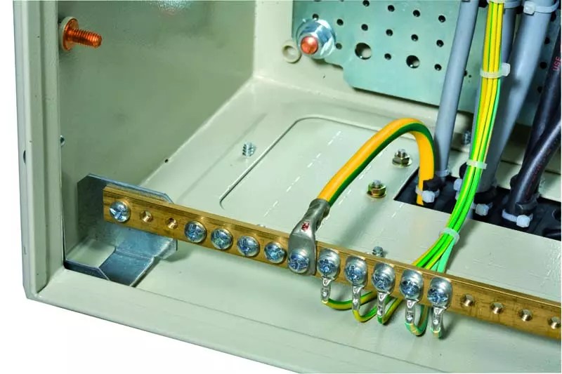
Electrical shield. Separately, we see an earthen vein that is in contact with the shield due to the standard bolted connection located on the shield door.
And now what we have left behind the scenes, that is, underground.

Where we decided to bury the ground loop, we tear off a moat in the shape of an equilateral triangle - external dimensions 1.8 x 1.8 x 1.8 m, width - 40-50 cm, depth 1 m.

Accurately marking three points, between which the distance of 1.5 meters we hammer in the electrodes - 3 steel, 3-meter corners. This is where you really have to work hard. Corners on one side can be sharpened with a grinder - for better entry into the ground. Corners must be hammered strictly vertically. It will be necessary to drown them at half the height of the moat, that is, half a meter from the ground level, it will turn out deeper - please, it will only be inconvenient to carry out welding work.

We carefully weld three one and a half meter corners to the electrodes hammered into the ground - the corners, we weld all adjacent planes well.

Then, you need to measure the resistance of our grounding. For reference, the maximum allowable resistance for a single-phase wiring system is 30 ohms. Special, competent services in this matter hammer 2 electrodes into the ground and check with their device. For us, in order to be sure that the contact of our circuit with the ground is good and the resistance does not exceed the permissible parameters, that is, our work is not in vain and the grounding device with our own hands in your private house will be really reliable, you need to do the following:
Find in the house closest to the place buried steel structure socket and use the indicator to determine the phase.
Ground resistance test

Then take a lamp with a cartridge and power one of the lamp contacts from the phase in the socket, and connect the second to the ground loop. If the lamp burns brightly, then the connection with the ground is good and the resistance does not exceed the permissible values. If the lamp burns dimly or does not light at all, then the resistance exceeds the permissible values, such grounding will not protect the house. It will be necessary to increase the area of the ground loop and check again.

If the test is successful - the lamp burns brightly, the resistance is acceptable, then we weld one end of a metal 14 mm rod to the steel corner of the ground loop and lay it to the house in the ground. Then we lift it under the pediment and commute with at least 4 copper squares from the core and lay it in the shield. In the shield, we connect the earth to the body of the shield using a standard, bolted connection and distribute the earth among household appliances and sockets. We return the excavated soil to the ditch.

A lightning protection device, when the ground loop is ready, will take a little time and save you from possible troubles.
Typical grounding device error
In this video, the grounding device is made, say, with a C grade with a plus. Reinforcement or corrugated metal is not used as electrodes or metal driven into the ground, since by its properties it is not able to stay in an aggressive environment for a long time - this leads to its inevitably rapid corrosion, respectively, such grounding will fail quickly enough. When using a rod, only a smooth surface is justified. And the method of hammering metal into the ground with the help of a perforator, frankly, pleased me, for this respect to the author.