We tinker, we solder, we fix iPads. We knit harnesses from wires Installation of connecting devices
It's nice to have a girl in our midst. Her name is Elena. She is from the city of Rybinsk, Yaroslavl region. Here is what she writes about herself:
Good afternoon! I want to write about electrical harnesses for cars and motorcycles. Do's and Don'ts available materials, personal experience. I work as a design engineer, designing harnesses and wiring for piston engines.
So, Elena's article.
About electrical harnesses
A harness is a set of electrical wires and cables that are used to connect various elements of electromechanical or electronic systems.
The purpose of the harnesses is to provide power or transmit electronic signals to various peripherals. The harness consists of at least two wires.

Photo 2 - Harness on the assembly table (www.knaapo.com)
This is what professionally made car harnesses look like:
Subscribe! It will be interesting.

Photo taken from JDMParts blog on drive2.ru
This is what aviation harnesses look like (aer.interelectro.com.ua):


Materials and components for the manufacture of harnesses
The materials used in aircraft harnesses are highly reliable and can also be used in military equipment. For example, heat shrink tubing from Raychem and Deray. After shrinkage, they are quite soft (unlike cheap tubes), resistant to abrasion.
Separately, it is worth mentioning the connectors used. For Russian technology, cylindrical and rectangular connectors are used, for example: SNTs, RSTV, ONTS-BS, 2RMD, 2RMDT (photo 6), in a metal case.

Any harnesses consist of the same components:
– wires (power and signal);
– connectors, lugs, terminal blocks;
– protective materials (winding tape, corrugated and heat-shrinkable tubes, protective sheaths and stockings);
- harness fastenings (clamps, holders).
The difference in price between special materials and what we use for ourselves - at home or in the car - at times.
There are many specialty electrical materials, but they tend to be very expensive or rare. And often we simply do not know what to use (this applies to materials and tools) in specific situation and here begins the "collective farm".
Wires for making bundles
Where do we start? From wires. When choosing, be sure to pay attention to the operating temperature, insulation resistance to gasoline, oil, and combustion resistance.
Take stranded copper wires in isolation different color and different sections, for example PV-3. They withstand temperatures from -50°C to +65°C. They are quite common, they are in online stores and in retail. In fact, these were the only wires presented in a wide range colors and sections that were found in a store in my city. Unfortunately, this is usually the case.
(photo 7).

Photo 7 - Materials, tools and wires for the production of harnesses
You need to cut off the required amount. You can measure the length with a rope or wire, laying in place. It is necessary to leave a margin in length for triple re-embedding into contacts or lugs (a few centimeters from both ends). After twisting, the wire will become even shorter, do not forget. The wire should not be taut, especially near the connectors. If you are not sure - take a longer one, you will always have time to cut it off.
In general, if the wires go together at least 50 mm, they are combined into a bundle. It is forbidden to lay power and signal lines in one bundle. This means that the wires from the sensors and the wires from the powerful consumers should follow different paths and be as far apart as possible. An extreme case is a wire from a sensor and an armored wire from a candle.
The winding of the wires can be fixed with a tape or a special thread. FUM tape is available for household practice (in industry, SKLF-4D fluoroplastic film is used, FUM tape is also made of fluoroplastic, a non-combustible electrical material). The winding is carried out in the opposite direction of the winding. (photo 8).
And what's fresh in the VK group SamElectric.ru ?
Subscribe and read the article further:

Photo 8 - twisted wires
Stranded wires are more flexible than just folded together and covered with some kind of sheath.
The upper shell is corrugated, heat-shrinkable tube.
These are the most common materials used in private practice to protect wires. Sometimes they wrap the wire with electrical tape along the entire length, this is not necessary. The glue decomposes over time (especially from heat), the wire will remain sticky, in the end it does not look very good (photo 9).

The corrugation is split and continuous (with a probe for broach - wire). Split can be put on a ready-made harness with installed connectors.

There is no need to fill the entire corrugation with wires, let there be some free space (for more details, see clause 5.9 - GOST 23586-96) In the end, you may need to lay a few more wires. Sometimes they put spare wires in the bundle, their ends must be closed, because. the wire is a capillary pump, liquid getting inside will cause corrosion.
Photo 11 shows a way to seal the insulation of a spare wire, it consists in the fact that a piece of heat shrink (the presence of an adhesive layer is not important) is put on so that at least a centimeter and a half is not put on the wire and treated with a burner. Until it cools down, we squeeze the free part of the tube with our fingers, it will stick together. All.

The use of heat shrink in the production of electrical harnesses
It would seem that the split corrugation is leaky, what is the use of it? It will not allow the wires to fray on sharp edges, unlike inexpensive heat shrink. There is a minus - the corrugation will not withstand a high temperature.
Instead of a corrugation, a tourniquet along the entire length can be put on heat shrink.
Conventional heat shrink HERE has an operating temperature of -55 to +105°C, a shrinkage ratio of 2:1. This means that a size 8/4 tubing has a diameter of 8 mm before shrinking, 4 mm after shrinking. The closer the diameter of the bundle to the diameter of the unshrinked tube, the smaller the wall thickness after shrinkage, therefore, it is worth choosing a tube so that the diameter of the bundle is approximately in the middle of these dimensions.
To seat the tube, you can use matches, a lighter, a burner, a building hair dryer. The main thing is to monitor the uniformity of shrinkage and not burn it (for any tube, the manufacturer writes the temperature of its full shrinkage). It is inconvenient to do this with matches. Honestly. A small tube can still be seated at the soldering point of one thin wire, something more can not.
Professional option - (actually a good thing, great for working with wood and leather when waxing, helps to remove old paint, will heat the part when replacing bearings). It has a temperature control over a wide range, shrinkage is even and not too fast.
I use a soldering torch, it is filled with gas for lighters (photo 12).

The flame has high temperature, so you need to do everything quickly and carefully so as not to burn the tube. On my own, I recommend purchasing such a burner, it will help when working with heat shrink, when soldering massive parts, and in other cases. But you can do without a hair dryer.
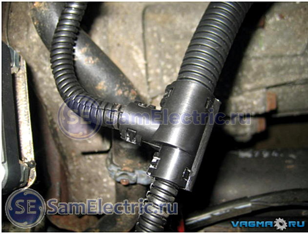
The branching of the wires hidden in the corrugation is carried out using a collapsible tee (photo 13)

I didn't have any triplets. I had to use tape, even though I don't like it. The edges of the tubes are inserted into each other and carefully wrapped.

For branching, there are cable heat-shrinkable cable gloves (photo 15)

Photo 15 - cable heat-shrinkable gloves
It's a great thing, but I've seen these in retail stores once, and then they are designed for large diameter cables. If you are a fan of your craft, you will surely want to use these products. They are in online stores (but you have to look), for example, the KBT plant (Kaluga) will soon produce such products (I advise you to visit the KBT catalog on their website).
Stripping

Photo 16 - Stripper
It is carried out with a special tool - a stripper (photo 16)
He cuts the insulation, not reaching the core, but so that it can be torn off and moved. I strongly doubt that someone uses such a tool in everyday life (for example, I don’t have one). Do not listen to someone who tells you “and I cut the insulation across the wire with side cutters / cutters / knife” this is done at your own peril and risk, you cannot be sure that the blade did not reach the wire cores. "By eye" it is very difficult to adjust the depth of the incision.
I do like this. But you need to be confident in your tool, hands and wire insulation! Yes, and after 10-20 such removals, corns begin to appear! (Note SamElectric.ru)

One of the stripping tools is a mounting knife, straight or with a heel (photo 17). With some skill, insulation can be used with a clerical knife instead of a straight mounting knife. The insulation is cut with chips, as if sharpening a pencil, but trying not to cut the wires.

I use a utility knife extensively. Especially when stripping cables. To do this, I cut the outer insulation lengthwise, trying not to cut the inner, individual one. And in a single wire I remove the insulation (when there are no wire cutters, or in difficult cases), cutting the insulation around.
Defense companies used insulation burners, which are similar to wood burning tools. With a hot nichrome wire, the insulation is burned in a circle and then removed. Suitable for MGTF and other wires. Similarly, you can remove the insulation with a soldering iron (photo 19). Minus - the smell and harmful fumes.

Photo 19 - Removing the insulation with a soldering iron.

Photo 19-2 - Removing the insulation with a soldering iron.
Soldering or crimping wires
In general, crimping is better in terms of vibration resistance. When soldering, at the point where the wires come out of the solder, they are more likely to break off if they are subjected to vibration (photo 20).

A properly made crimp is stronger than the wire itself, but how many people have a crimp at least for auto-terminals at home? That's right, no, I have too (but in general the crimps look like this - photo 21). So let's solder.

I have both a crimp and a stripper. I already wrote about crimping wires with tips.
Important: never use acidic fluxes when soldering wires, no matter how tempting it may sound. Because the wire is a capillary pump and you still can’t wash out the flux residues from there, no matter who tells you what. Soon there will be corrosion.
It is convenient to use rosin dissolved in alcohol. Pour this solution into a bottle with a brush, such as nail polish.
It is convenient to use flux LTI-120 with a brush. Or rosin in a jar, I write about it.
Connector covers
- protect the contacts inside from water and dust, provide mechanical adhesion of the connector body and wire. They are sealed or non-sealed.
In the photo 22 connector long time worked without a casing, the wires were often bent and moved, the cores were partially broken near the contacts (the wires were connected by crimping, but the cause of the malfunction was precisely in the absence of a casing).

Photo 22 - Connector without casing
Sealed casings are made of heat-shrinkable materials with an adhesive layer. The same tube, just a different shape. You can easily use a piece of regular tubing, but the fact is that the diameter of the back of the connector and the diameter of the cable have a very large difference that ordinary heat shrink at a ratio of 2:1 does not cover. Simply put, it will sit on the connector normally, and the wire will hang out. You can look for tubing with a shrink ratio of 3:1 or more. They do exist, but they cost more.

23 - Heat shrink connector cover
In photo 23, a piece of ordinary heat shrink was used, a corrugation of a larger diameter was taken (only 2 wires inside). It should be noted that the softening temperature of the corrugation is approximately equal to the shrinkage temperature of the tube, so you need to work with the burner quickly and carefully, trying not to overheat anything.

Photo 24-1 - Before and after

Photo 24-2 - new electrical harness installed
Sealing
If necessary, special mastic is poured inside the casing to seal the contacts. In private practice, you can use silicone automotive sealant. Large volume will dry for several days. If this is really necessary, try to be patient and pour in parts, or at least smear the critical parts with a thick layer.
Important: never use acid curing sealants, corrosion will not take long.

If you open the tube and the smell of acetic acid hits your nose, do not use it. If it does not smell, you can use it, it is alcohol-based neutral.
As a rule, acid sealants are cheaper (ABRO, RUNWAY), an honest manufacturer will indicate on the package - “Contains acetic acid”. If there is no such inscription, carefully read the composition and google each of the components. The composition of the sealant that I bought contained methyltriacetoxysilane - this is a reagent for vulcanizing rubbers, synthesized using acetic anhydride (I do not claim that this component is present in absolutely all acid sealants, please pay attention to the composition when buying).
After opening this tube, it began to smell of acetic acid, although the manufacturer indicated that it could be used for electrical connections. We will not tempt fate, we will leave it for less responsible nodes.

Bundle laying
The installation order is:
- we place the tourniquet in place, temporarily fix it with ties;
- connect everything electrical connectors;
- we fix the bundle in place, starting from the connectors (for example, from the ends of the bundle, where there are smaller terminals to a large common connector).

The harness is secured in place with nylon cable ties. By the way, black ties are more resistant to external influences.
In photo 27 on the left you can see 2 metal clamps that attach the wires to the frame. They can be used, but on condition that the clamp does not fray the wire - locally wrap it with electrical tape, put on a piece of heat shrink, put something on it. Do not forget that the harness should not be pulled tight at the connectors, should not touch sharp corners, dangle too much, or touch very hot parts.
But what if the harness goes into the box and connects there?
This situation simply occurs when a brake light is connected:

The black contraption with a union nut in photo 28 is a plastic cable gland (gland). It is designed just for entering cables into various boxes. Such a thing costs no more than 20 rubles (for small wire diameters). There are metal cable glands (for harsh conditions and critical connections), but in stores they are at best made to order, the cost is already about 100 r per piece. In addition to the inputs, there are special penetrations and bushings.

Photo 29 - Cable entry on the wire in the analysis

The wire dangles in the connector (yes, anywhere), what else can be done?
If winding with various electrical tapes (PVC or fabric) and fixing with clamps does not suit you, then ...
There is such a wonderful thing - LETSAR silicone tape - electrical insulating heat-resistant self-adhesive rubber radiation vulcanization tape. It is a self-adhesive tape, vulcanized at room temperature. After two days, you get a piece of relatively soft rubber where you wound it.
In aircraft harnesses, it is just wound under rigid metal casings for better compression. I will not describe the properties in more detail, too much text. Sold in spools of 500 g, highly stretched when winding, the coil will last a very long time.
In general, it is worth looking for self-adhesive (self-vulcanizing) tapes of other brands, there is less packaging.
- OST 1 00723-74 Connection of negative wires to the aircraft body. Technical requirements
- GOST 23585-79 Installation of electrical radio-electronic equipment and devices. Technical requirements for cutting and connecting wire screens
- GOST 23586-96 Installation of electrical radio-electronic equipment and devices. Technical requirements for harnesses and their fastening
- GOST 23587-79 Technical requirements for cutting installation wires and fastening cores
- OST 1.01025-82 Shielding of wires, bundles, cables and metallization of aircraft. General technical requirements
Cable tie add-on
It is more practical than plastic ties (clamps) and electrical tape. The main advantage is that it is reusable!


Simple, cheap and beautiful to clean up the wires inside your electronic structure.
All you need is an empty soda bottle, scissors and a kettle. How to do this, read on.
When disassembling factory designs, everyone probably saw that the wires were tied into bundles.
AT makeshift designs this is rare. It often happens that behind a heap of assorted wires, the boards and other elements of the circuit are barely visible. Often such a pile of wires can be seen inside system block computer, where the wires from the PSU and signal bus fill the entire interior and impair the cooling of the components, often dangling wire stops one of the cooling fans, which leads to overheating and failure of expensive components.
Using the example of making a braid for wires of a computer PSU, I want to show how at home to quickly and cheaply tie the wires of your electronic structures into bundles, those who wish can thus put things in order in the wires inside their system unit.
So what do we need.
empty plastic bottle from soda. I used a poisonous green Mountain Dew bottle. This plastic glows brightly in ultraviolet light. To decorate the insides of the system unit with a window on the side surface and UV backlight lamps inside - it’s better not to think of it. For tying into a harness inside an amplifier or some other design, any bottle of the color you like is suitable.
We cut off the neck from the bottle and with scissors we cut a narrow tape about 3-5 mm wide in a spiral.

Then we tightly wrap the wiring harness with the resulting tape. To prevent the tape at the ends from untwisting, we fasten it with temporary wire ties. You can use nylon ties or pieces of heat shrink tubing. It is necessary to wind a coil to a coil, pulling as tightly as possible.

And now the most important thing. Surely everyone is aware that the plastic from which the bottles are made has pronounced heat-shrink properties. If you don’t know, then just try pouring boiling water over the bottle to see for yourself. After wrapping the wiring harness with a tape cut from a bottle, this tape must be warmed up. I used a hair dryer set to blow air at about 130c*. If the wiring harness has not yet been unsoldered, or you decide to ennoble the wires from the computer PSU in this way, then you can use the hot stream of steam coming from the spout of a boiling kettle. Only then do not forget to dry thoroughly from condensed moisture.
The rest of the photos were taken with UV light in a darkened room to make the braid stand out better.
After being treated with heat, the braid will shrink, tightly wrap around the wires and fix its shape, it will no longer try to unwind. The wire ties securing the ends of the tape can be removed. Wires in such a braid become rigid. They are easy to shape and hold well.

I hope that this simple and cheap method will allow you to clean up the wires inside your electronic devices and may be useful to someone to decorate the interior of your system unit or some other device with transparent windows in its walls. Good luck!
Making and laying harnesses
The bundle is a collection of stripped wires and cables fastened together in some way and, if necessary, equipped with elements electrical installation(tips, connectors, etc.).
According to their purpose, harnesses are divided into intrablock and interblock.
Intra-unit harnesses are used for electrical connection of individual units, blocks and electrical parts inside the device, and inter-unit harnesses are used for electrical connection of various radio equipment and devices into a single system. Depending on the location of the nodes in the body, the bundles can be flat or voluminous.
To protect against exposure environment, mechanical damage or for the purpose of shielding, the bundles are wrapped on the outside with a keeper, nylon, lavsan or polyvinyl chloride tape, varnished or enclosed in a shielding braid.
1) different colors of wire insulation;
2) coloring or numbering of PVC tubes used to fix the ends of the insulation (the tubes are numberedon the machine, in special stamps or inscribed by hand with marking ink);
3) plastic tags with a symbol for the connection point, put on the wires.
Harnesses in which failed wires cannot be replaced are provided with spare wires. Their number is taken at the rate of 8 ... 10% of the total number in the bundle, but not less than two wires. The length and section of the spare wires must be equal to the largest length and section of the wires present in the bundle. The length of the harness leads must be sufficient for connection to the nodes and elements of the device circuit without tension; in addition, there must be a margin of 10 ... 12 mm for re-stripping and attaching each end of the wire.
A typical technological process for manufacturing a tow includes the following operations:
cutting wires and insulating tubes;
laying wires on the template and knitting them into a bundle;
termination of the ends of the wires of the bundle with their simultaneous marking;
harness control (continuity); protection of the harness with insulating tape;
output control (visual inspection for compliance with the standard, well, and continuity).
The length of the prepared wires must correspond to the dimensions specified in technological map or a table of wire blanks. Wires and shielding braids are cut on automatic machines, as well as using assembly or guillotine scissors and wire cutters.
It is more expedient to make a blank of wires of the same length and knit them into a bundle without branches on a special device (Fig. 1.25), which consists of two racks mounted on a board (the distance between the racks depends on the length of the prepared wires).
On the outer sides, the racks have grooves. First, the wire is wrapped around the posts, while the number of turns of wire should be half the number of wires in the bundle. Then the coils of wire located between the uprights are tied into a bundle with thread or twine. After tying, the turns of wire are cut in places located opposite the grooves in the racks.
With the manual method of harvesting wires for bundles, their length is determined using samples or a ruler. In serial production, special machines are used for measuring wire cutting to a predetermined length.
The wires are laid on the template in a certain order (according to the scheme printed on the surface of the template), after which they are tied with a thread or twine into a bundle. Template markup forthe wiring harness is laid according to the wiring diagram, the layout of the node or device in which the harness will be installed, and the mounting table of connections. On the marked template, the wires are first laid out and then knitted into a bundle (Fig. 1.26). Depending on the design of the device, the bundles are flat or voluminous.

When laying out, the ends of the wires are cut along the transverse "marks, marked and fixed. The laying of wires on the template starts with spare and long working wires and ends with the shortest wires. Shielded wires included in the bundle are wrapped with keeper tape and placed inside harness or in an insulating tube.
The harness should be knitted in one direction with cotton thread No. 00 or linen No. 9.5/5. For hand knitting, the device shown in Fig. 1.27 a. A spool 3 with threads is inserted into the body 4 of the device. Covers 5 and 2 serve to center the coil. In the top cover 5 there is an eye for giving the thread a certain direction, and a hook 1 is attached to the bottom cover.

To facilitate the winding of the thread from the spool, a slot and an outlet for the outer end of the wound spool are made in the body. First, a wound coil is inserted into the body of the device, the upper end of which is inserted into the slot of the body. Next, the lid is closed and the end of the thread is threaded through the eyelet.
The harness is knitted in accordance with the loop formation scheme. It takes 0.5 ... 1 s to knit one knot. To perform the operation, it is necessary to take the thread (see Fig. 1.27, b), hook the loop, stretch it under the tourniquet and thread the device through two loops, tightening the thread. At the moment of tightening the knot, the thread passing through the body must be pressed with a finger to its surface. The device helps to improve the quality of knitting harnesses and reduce the complexity of their knitting by 15...20 times. Recommended knitting methods are shown in fig. 1.28.
 Loops are recommended to be knitted with tension at regular intervals (no more than 50 mm), as well as in places where wires branch off.
The knitting step of the loops is set by the designer, depending on the diameter of the bundle.
After knitting the wires into a bundle, their ends are terminated. First, all ends of the wires are marked according to the wiring diagram, and then the correct layout of the wires is checked with a dial tone. In the case of using electrified templates for making harnesses, continuity can be omitted.
The control of complex harnesses is carried out on special semi-automatic stands according to a given program. The harness on the panel of the stand is fixed manually, and the correct layout of the wires and the resistance of their insulation are controlled automatically.
First, compliance is checked electrical diagrams connections, i.e. checking the correct layout of the wires. For this purpose, the required voltage is sequentially applied to one of the ends of the tested wire. With the correct layout of the wires, the voltage should be fixed in all wires of the bundle electrically connected to the wire under test. Next, you need to make sure that there is no voltage in the wires of the bundle, which are not electrically connected to the wire under test. All information about the control is issued automatically in the form of coded holes on a punched tape or as a record on a tape with digital and alphabetic designations.
When monitoring the insulation resistance of wires, a consistent supply of constant voltage is automatically carried out to electrically isolated wires (circuits), while fixing the insulation resistance.
If necessary, the harness is protected with insulating tapes or a shielding braid. Finished bundles are laid according to the wiring diagram and the drawing of the device. Simultaneously with laying, the ends of the wires of the bundle are bred to the corresponding places in the device circuit and soldered. At the same time, it is necessary to ensure that individual wires do not obscure the markings and inscriptions of the nominal values on the parts.
Attention! When laying the harnesses in the device, care must be taken to avoid breakage and breakage of the conductive cores of the wires and conclusions of the hinged radio components, as well as short circuiting of bare conductive places.

Inside the device, the harness is attached to the chassis or walls with metal brackets (Fig. 1.29), under which you must firstput insulating materials made of polyvinyl chloride, varnished cloth or pressboard. The edges of the gaskets should protrude from under the bracket by at least 5 mm. The brackets are made double-sided (attached with two screws) and one-sided (attached with one screw). The design of mounting brackets, especially single-sided ones, must be sufficiently rigid to prevent them from bending or deforming when attached to the chassis together with the harness.
To ensure the transition of unshielded (and, if necessary, shielded) harnesses from one unit of the device to another through the wall of the chassis or screen, insulating bushings are provided in this place.
Cars are currently subject to high requirements for build quality and reliability. Accordingly, each unit and part of the car must meet these requirements.
An integral element of the car is the electrical wiring (wiring harnesses). A wiring harness is a finished product consisting of individual wires fastened together in a bundle, the ends of which are reinforced with contacts that are assembled into blocks or protective elements (tubes, rubber caps, covers) are put on them. The wires are fastened into bundles: bandages made of PVC adhesive tape, cable ties (toothed clamps made of thermoplastic polymers); heat shrink tube.
 A modern car has harnesses with a total number of wire segments of about three hundred (and more often more), reinforced with various contacts. The reliability of such a complex product depends on several factors. First of all, these are increased requirements for the quality of components and materials. Which, in turn, is influenced by the choice of supplier and the conduct of incoming control.
The next factor is the use of modern high-performance and precise production and control - measuring equipment that meets the requirements international standards. And, finally, the most important factor of reliability is the specialists involved in the production process. The quality and reliability of the product depends on their professionalism.
Autotractor harnesses can be divided into: low and high voltage wiring harnesses (battery and starter wires are most often single, less often - consisting of two or three wires).
 Technological process the manufacture of a wire harness is divided into several basic operations: cutting wires, stripping the ends of wires from insulation, reinforcing wires with lugs or contacts, fastening wires into bundles (binding), installing plug-in connectors, quality control.
In order for you to better understand what components the wiring harnesses consist of and in what sequence they are used in their manufacture, we tried to give detailed description basic operations for the manufacture of harnesses and types of equipment used.
For a better understanding of the assembly sequence of any bundle, in this section we will introduce general concepts bundle structures, which will be found later in the text. The harness can be divided into parts and give them names.
- Harness trunk - part of the harness with the largest number bundled wires.
- Branch - a bundle of wires extending from the trunk of the harness or other branch.
- Branch point - the place where two or more bundles of wires diverge at some angle (s).
- Tips - elements that allow the installation and dismantling of a harness with cold contacts.
- Connecting devices - devices complete with lugs that allow simultaneous connection of one or more pairs of "pin - socket".
- Protective elements are rubber products intended for mechanical and chemical protection points of connection of the tip or connecting device with devices and other electrical equipment of the vehicle.
Harness manufacturing operations.
If you put together the elements that make up the bundle, then they would look something like the one shown in the photo (Fig. 2.) To assemble a bundle from them, you first need to know the sequence of operations for assembling the bundle. The manual assembly sequence (Fig. 3) for a non-serial harness is described below:
Wire cutting.
Wire cutting is carried out using manual fixture or wire cutter. Depending on the program for the production of bundles, a manual or automated cutting method is used.
Bonding wires into bundles (knitting).
 The wires in bundles are fastened with bandages made with PVC adhesive tape according to GOST 16214 - 70, cable ties (toothed clamps made of thermoplastic polymers according to GOST 22642.3-80) manually or using a special tool, by welding the wires laid out on the same plane to the fastening element made in the form of a PVC tape or one of the wires of the zigzag bundle.
By agreement with the consumer, wires in bundles can be protected and bundled with a PVC tube, wrapped with PVC adhesive tape, spiral tape or corrugated tube.
The PVC tube and the spiral tape on the bundle must be fixed with a bandage or in other ways that exclude its movement and unwinding, respectively. The ends of the corrugated tube are usually protected by a heat-shrinkable tube or special rubber covers, which are selected according to the diameter of the tube.
Bandages are also applied at each branch point and on the branches themselves in such a way that the distance between the bandages is no more than 250 mm, if the distance is not indicated on the drawing. A splitter is installed on the bundles in the corrugated tube at the branch point to prevent the tube from moving at the junction and to protect the branch point from mechanical influences.
Stripping the ends of the wires from insulation.
Insulation stripping is performed automatically, when cutting with a dimensional cutting machine, or manually using wire stripping pliers depending on the harness release program. The use of machine tools and special hand tool guarantees high-quality stripping without insulation residues and without cutting copper wires.
Reinforcement of wires with tips.
 Reinforcement of wires is made by method of cold pressing in the manual or semi-automatic way. This method ensures reliable contact of the wire with the tip. The cross section of the wire in the place of the molded tip has the shape of a "heart". Each strand wire is deformed, losing its round shape, filling the voids and thereby providing the maximum contact area with the tip. Tips corresponding to normative and technical documentation are used to ensure high-quality contact.
The use of modern presses provides reliable mechanical connection, the breaking force of which meets the requirements of GOST 23544-84 and is controlled by special devices.
In the manufacture of battery and starter harnesses, after pressing, tinning is used. It gives a better electrical contact, a more reliable mechanical connection and protection against corrosion. The overestimated requirements for the quality of the connection of the tip with the wire are explained by the fact that the place of contact between the wire and the tip experiences an increased current load and thereby increases the heating of the contact area. During operation, this can lead to wire breakage, short circuits, or even wiring fires.
Installation of connecting devices.
After reinforcing the wires with lugs, connecting devices (blocks, connectors) are installed where they were provided.
This article defines the rules for working with the electrical wiring of a car.
This document consists of 2 main parts:
- The first part deals with general repair methods
- The second part provides cases of applying these methods to eliminate specific faults.
Special tools and fixtures:
- Tool for removing and installing clamps and connector latches.
- A device for restoring the insulation of wire harnesses.
- soldering iron
2. General rules
General rules to follow:
- Repair work must be carried out by trained personnel authorized for such work.
- After the repair is completed, all functions electrical system affected by this electrical circuit must be checked
- Splicing of 2 wires by soldering using tin is prohibited (rigidity, possibility of breakage)
- Optical cables and armored cables must be replaced in their entirety if crushed or broken.
- After analyzing the malfunction, its cause should be eliminated.
- Wiring harnesses can be repaired
MANDATORY: When working with pyrotechnic devices, follow the manufacturer's instructions (which can be found in manuals and reference books or on the manufacturer's information website on the Internet).
MANDATORY: Disconnect the battery when doing any work on the electrical wiring (Including backup power supplies if installed).
3. Repair methods
3.1. Wire Test Method
The wire test procedure aims to determine whether a repair can be made directly on the damaged wire, or whether a portion of the wire needs to be replaced.
The wire is considered unsuitable for further use in the following cases:
- The wire is not long enough to make a repair that does not cause further strain on the wire or friction that will damage the insulation or break
- The wire has insulation damage, tearing or crumpling over a considerable length
- The wire burned
- If the wire has come out of the molded connector block and the length of the wire that can be used is less than 30mm
In all other cases, the wire can be used.
3.2. Wire Selection Method
Cases when the wire cannot be used:
- The cross section of the wire used for repair must be equal to or greater than the cross section of the wire being repaired, but in no case less than
- "mass" wire must have a specific color
3.3. Wire stripping method
After cutting the wire, strip the end without damaging the core using a certified tool, respecting the following length of the stripped end:
- 8 mm, plus/minus 1 mm for in-line connection with "RAYCHEM" coupling
- 15 mm plus/minus 1 mm to be inserted into the "RAYCHEM" sleeve when splicing parallel stranded wires
3.4. Tin soldering application method
It is allowed to use tin soldering to strengthen poor-quality wire splices (too large electrical resistance) subject to the following requirements.
Required tool:
- Soldering iron with clean tip
- Tin 0.7 mm
Work mode:
- Set the soldering iron temperature control to position 6 - 7 (310°C - 370°C), do not go beyond position 7
- Pick up some tin on a soldering iron tip
- Treat the place of twisting with a soldering iron tip, the twisted ends should remain visible
- Solder the tin wire to the copper core of the wires at the ends of the splice (solder consumption approx. 3mm)
It is important not to apply too much tin (risk of hardening the wire) so as not to destroy the insulation and the connection.
3.5. Disconnecting connector latches
IMPERATIVE: In case of cold temperatures, move the vehicle to a heated room with a temperature of approximately 20 °C before starting work.
Disconnection of the connector lock should be done using the tool included in the certified kit, following the instructions for use included in the kit.
ATTENTION: Be careful not to damage the connection, connector terminals, terminal sockets and ensure that the connector is sealed during installation.
3.6. Connector Selection
In case of replacement of a connector or a connector terminal, the same elements (gold-plated or tin-plated terminal) should be used.
3.7. Inserting the connector terminal into its socket
Terminal installation:
- Visually check the condition of the terminal and block
- Insert the terminal into the socket
- Install the connector locking latch (Depending on equipment)
- Lightly pull on the wire
- If the terminal is not held in the socket, the socket must be replaced.
3.8. Compression fitting
To repair a connection using a crimp sleeve, use only the tools and parts included in the certified kit.
If the repair requires the use of several couplings, keep the distance between them so as not to increase the volume of the connection.
Repair with an additional piece of wire (2 sleeves), the wire cannot be used.
|
|
|

3.9. Installation of the coupling on a lay of two parallel wires
Use only tools and parts from a certified kit.
If multiple couplings are used, keep a distance between them to ensure a minimum connection volume.
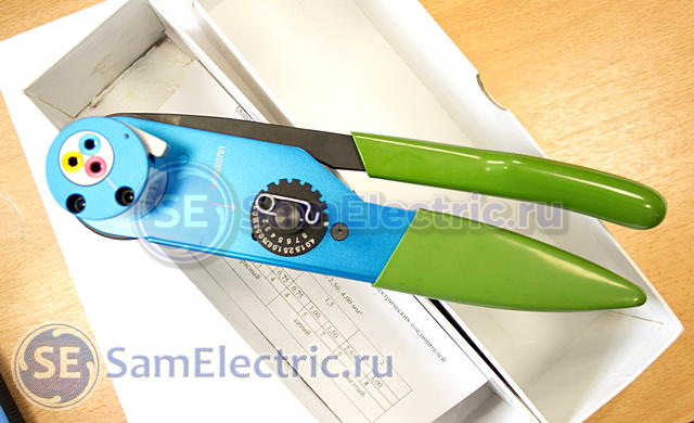
The choice of coupling depends on the cross section of the connected wires:
- Red ferrule: Wire from 0.35 mm² to 1 mm²
- Blue ferrule: Wire from 1 mm² to 3 mm²
- Yellow ferrule: Wire from 3 mm² to 5 mm²
Clutch installation.
Installation of 2 splicing sleeves for twisted wires; Install the wires coming from one side into the sleeve and those coming from the other side into the other sleeve (see the figure), making sure that they do not change their relative position (one wires in relation to the other).
To insert the wires into the shrink sleeve, turn it slightly.
Heat the sleeve with a certified hot air generator until a core of molten tin forms and excess adhesive appears.
Approximately 90 seconds should be allowed for the gun to preheat, approximately 1 minute for the sleeve to heat up depending on wire size, and 3 minutes for the gun to cool down.