Sighting range svd 7.62. SVD (rifle): characteristics. SVD target range. History of the Dragunov sniper rifle
This year, the entire weapons community celebrated a significant date - the 95th anniversary of the birth of the outstanding domestic designer of small arms - Evgeny Fedorovich Dragunov. The main business of Yevgeny Fedorovich's life, which required incredible stress for several years, not only creatively, but also physically, by his own admission, was the creation of a self-loading sniper rifle SVD.
Starting to develop a promising rifle, the Izhmash management appointed Dragunov as the head of the creative team for a reason, because he was already a mature designer, had considerable experience in developing target weapons and even received a government award (the Order of the Badge of Honor) for its creation. In this issue of the magazine, we begin the publication of a series of articles designed to highlight the history of the creation of the most legendary sniper rifle of the 20th century, which is still guarding the Fatherland.
The profession of a designer-gunsmith is ungrateful by its nature: after all, in this area of creative activity, unlike, for example, sports, even second place is tantamount to complete defeat - there is only one step on the “pedestal of honor” and there is no place for the second. So any development work is not only an exam for professional competence, but also a test of the measure of the designer's talent.
The fact that there are no “silver” and “bronze” medals in weapons design and development works, apparently, leaves its mark on the character of gunsmith designers. Most of them are extremely closed, laconic, have "dictatorial manners" and are somewhat far from ordinary worldly joys and human weaknesses. The personality of E.F. Dragunov fits into this stereotype exactly the opposite way - sociable, talkative (a wonderful storyteller), friendly not only with colleagues, but also with competitors, completely devoid of swagger and rudeness, cheerful and soul of any company, not alien to simple human weaknesses.
Probably Evgeny Fedorovich was lucky when in 1958 a competition was announced for the creation of an army self-loading sniper rifle, because he already had serious experience in developing target sporting weapons and an army non-automatic sniper rifle. If he had participated at that time in the competition for the creation of a single machine gun, the entire history of weapons would apparently have changed its trajectory. And so, having proven fundamental principles for building weapons for accurate shooting, Dragunov was "at the right time in the right place." It remained "nothing at all" - to work out the automation and make the layout of the sample. This is where the talent of the designer, who presented a largely revolutionary model of a rifle, manifested itself in full. But the victory did not come “suddenly”, the main competitor turned out to be also “not a bastard” and promoted a no less innovative concept for building a sample. So, in order.
In service with the Red Army (later the Soviet Army) from the beginning of the 30s, a 7.62-mm magazine rifle arr. 1891/30 Mosin designs. Repeated attempts to replace it with more effective automatic weapons were not very successful for a long time. The sniper rifles of Simonov (1936-1938) and Tokarev (1939-1942) did not stand the test of time, because inferior to a magazine rifle not only in terms of trouble-free operation, but also in terms of accuracy. Attempts to develop sniper rifles were also unsuccessful in the first post-war years (Simonov's 1945 self-loading rifle and KB-21946 self-loading rifle). In the early 50s (1949-1950), the possibility of using the 7.62-mm Simonov self-loading carbine (SKS) as a sniper was also tested. However, as a result, it was found that the 7.62-mm cartridge mod. 1943 does not allow creating a sample with the required bullet dispersion characteristics. At the same time, in the conditions of a difficult international situation that threatened the outbreak of another world war, this issue was more than relevant.

7.62 mm self-loading sniper rifle mod. 1891/30


The share of sniper fire in the unit does not exceed one percent, but the effectiveness is inversely proportional. The experience of the Patriotic War and the post-war ones showed that in the defense of a battalion company, out of the total number of targets hit by small arms, sniper fire accounts for 60-80%. Yes, and in the offensive, fire support for snipers, who timely detect and destroy the most dangerous targets, significantly reduces the loss of personnel.
That is why at the beginning of 1958, in the depths of the Main Artillery Directorate of the USSR Ministry of Defense (GAU MO), tactical and technical requirements (TTT No. 007596) were born for a promising sniper rifle and an optical sight for it. The deployment of work began immediately - on June 6, 1958, the Decree of the Council of Ministers of the USSR No. 609-294 took place, and on June 14 the order of the State Committee of the Council of Ministers of the USSR on defense equipment No. 200 was issued, which determined the circle of participants. The development of the optical sight was entrusted to plant No. 69 named after Lenin of the Novosibirsk Economic Council, and weapons - to the Kovrov OKB-575, Izhevsk Machine-Building Plant (No. 74) and Klimovsk OKB-180 at NII-61. Already at the beginning of 1959, all participants (leading designer of plant No. 69 A. I. Ovchinnikov with documentation for the PSO and PSO-1 sights, chief designer of the project from OKB-575 A. S. Konstantinov with the 2B-V-10 rifle project, the head of the sector of plant No. 74 E.F. Dragunov with the project of the SSV-58 rifle and the lead designer of OKB-180 S. G. Simonov with the project of the SVS rifle) were ready to defend the technical projects.
Their defense, very similar to the defense of diplomas by university graduates, was successfully held in the scientific and technical committee of the GAU on April 6 - all projects were allowed for further work, subject to the wishes and proposals of the commission. The concepts of building samples by each designer became clear to the customer. It's time to translate ideas into metal. And this task turned out to be not only difficult, but as time has shown, not feasible for everyone. The reason for this was the general course of development of weapons science. With the adoption of the Kalashnikov AKM and putting it into production to replace the AK-47, the requirements for promising models for the reliability of automation, resource and manufacturability of production were significantly tightened. Yes, due to the simplicity of design and ease of maintenance, Kalash already then became the criterion that is still relevant today. More "advanced" designers Konstantinov and Dragunov, perfectly understanding all the advantages and disadvantages of the "Kalashnikov" design, tried to weed out everything that hindered the achievement of the best results and bring something of their own into it, which was obliged to ensure the achievement of the final result. The third participant in the competition, Simonov, was unable to appreciate the principle of locking the bore with a rotary bolt, which was actively making its way to absolute recognition, stubbornly promoting its skew (already obsolete) and, in this regard, took the position of a potential outsider from the stage of defending the technical project.
All three were in solidarity only on three fundamental principles - accurate and trouble-free shooting can only be ensured by a rifle with a separate stock (butt and forearm are separate parts), built on the scheme of operation of automation with a short piston stroke, and the trigger mechanism to ensure ease of maintenance should be aggregate removable. None of the designers failed to take advantage of another characteristic feature of ensuring an accurate shot - ballistic studies showed that the best dispersion characteristics of bullets with lead and steel cores without damage to the barrel with a rifling pitch of 320 mm versus 240 mm for all regular systems chambered for a rifle cartridge, including including the regular sniper "mosquito".

General view of the 2B-V-10 rifle designed by Konstantinov of the first modification.

Incomplete disassembly of the 2B-V-10 rifle designed by Konstantinov of the first modification.


The development of design documentation, the manufacture of prototypes and their factory tests (including repeated ones) took a little more than six months. November 26, 1959 GAU MO in the person of assistant. the chairman of the scientific and technical committee issued an assignment to the small arms research range (NIPSVO) to organize field tests of promising sniper rifles. At the same time, a GAU curator was appointed - an experienced and competent officer, who, even in the post-war years, oversaw the development of machine guns chambered for mod. 1943 Engineer-Colonel B.C. Daykin.
OKB-575 was the first (December 11, 1959) to report readiness for field tests, notifying the GAU about the manufacture of four Konstantinov-designed rifles in two versions. The ideology of building the 2B-V-10 rifle, on which Konstantinov made a bet, seems commonplace from the standpoint of today - to reduce the vertical disturbing moments that occur when fired. For this, a low-profile gas outlet was used, and the comb of the butt was raised to its level. The idea is not revolutionary, but until that time it was rarely implemented. True, this had to be paid for with the exception of the possibility of firing using a mechanical sight with an optical one installed, and the development of a folding rack-mount sight (on which a rear sight can be mounted either with a diopter or with a slot) and a folding front sight base.
Structurally, the rifle is very simple and technologically advanced in production. The characteristic features of the design are: the receiver, consisting of two stamped halves (right and left), riveted to a milled liner into which the barrel with reinforcement is pressed (front sight base, gas chamber, front support ring of the forearm with a gas tube, sight block and rear support forearm ring). A base for an optical (night) sight is riveted to the left side of the receiver. In the lower part of the receiver mounted pistol grip fire control, safety bracket, magazine latch and butt checks latch. The receiver cover and recoil spring guide are mounted on a compact stock. A birch veneer plate curved along its profile is riveted to the cover of the receiver to ensure ease of application.
The device of the shutter and its parts, as well as the principle of their operation, are similar to the corresponding parts of the Kalashnikov assault rifle. The bolt frame of a very simple shape is a semi-cylindrical part, inside of which a rack is riveted to accommodate the bolt and a figured groove is formed to interact with the bolt leading lug. A reload handle is riveted to the front of the frame.
The principle of operation of the aggregate-removable trigger mechanism is the same as that of the AK assault rifle with a single fire. The transfer of the momentum of the powder gases to the moving parts after the shot was carried out in the same way as in the Simonov carbine - by means of a piston with a rod and a pusher.
The forend consists of two halves - right and left - which are fixed with the help of a movable front stop of the forearm (made integral with the gas tube) with a flag of the stop switch. The rifle does not have a gas regulator; instead, to ensure the stability of the cartridge case extraction force under various conditions, there are three semicircular (0.3 mm radius) grooves 52 mm long in the barrel chamber. Magazines for 10, 15 and 20 rounds have been developed for the rifle. To increase the practical rate of fire, the rifle is equipped with a slide delay.
Dismantling a rifle for maintenance, even from the standpoint of modernity, is very simple - after separating the magazine and checking for unloaded, unscrew the muzzle nut and separate the ramrod; by pressing the latch of the butt pins, separate the pin by holding the swivel mounted on it (the swivel, while remaining on the gun belt, insures the pin from loss); move backward to separate the butt with the receiver cover and return spring; separate the bolt carrier with the bolt from the receiver by sliding them back; turn the fuse box down and remove it from the receiver to the right; by pressing the trigger up, remove the trigger assembly from the receiver.
The first modification of the rifle (meaning the viable version, because in the process of its development, 5 prototype samples were made and tested at the factory) was born a month before the report on readiness for field testing. However, after the assembly of two samples, their mass turned out to be half a kilogram more than the specified TTT, and the management of OKB-575 decided to urgently refine the design. As a result, by December 11, technical documentation was worked out and two rifles of the second modification “thinner” by a pound were manufactured, which successfully passed acceptance tests. This surgical operation did not affect the details of automation, the buttstock, the cover of the receiver (shortened almost by half) and other not very important parts were beheaded. In addition, one of the rifles received four parts (two of which were a sight block and a front sight base) made of titanium alloy VT-5 instead of steel 50, which made it possible to gain another 77 g. 45 mm.


The Izhevsk Machine Building Plant reported to the GAU MO on its readiness for field tests on January 25, 1960. Some delay in terms occurred not through the fault of the designer or the plant, but due to the sending of the fourth prototype of the SSV-58 rifle for preliminary tests to the Klimov NII-61 (the previous three passed factory tests according to their program). Upon receipt of the reporting materials from NII-61, two samples for field tests were assembled and passed acceptance tests, which, together with the technical documentation, were sent to the landfill. At the same time, in the act of acceptance tests, despite the admission to field tests, delays in firing with fat-free parts due to the fault of stores were especially noted - jamming of two cartridges in the neck when filing the next cartridge. The way to eliminate them was also indicated - "... the defect is eliminated by increasing the depth of the notches on both sides of the magazine's neck."
Evgeny Fedorovich Dragunov saw the ideology of building a sniper rifle somewhat differently than Konstantinov. Initially, he redesigned the Kalashnikov locking unit, adding a third combat stop, rightly believing that this would allow more even distribution of the load from the shot, thereby reducing system fluctuations. The Kalashnikov-type butterfly valve (locked to the left with three lugs) received a striker lock to prevent inertial punctures of the primer. Structurally, it was implemented by a protrusion on the tail of the striker, a cutout on the shank of the bolt, transverse and longitudinal grooves on the inner surface of the bolt frame (the striker could only go beyond the bolt mirror when fully locked - to ensure safety when chambering a cartridge). As well as a damping spring to ensure safety at the moment of locking and in case of breakage of the protrusion of the drummer.
Dragunov's gas exhaust engine turned out to be even more low-profile than Konstantinov's due to the reduced piston diameter, but no less efficient due to the transfer of energy of powder gases from the piston to the bolt carrier instead of the two-link design like Konstantinov's 2B-V-10 and Simonov's S KS (rod piston - pusher - bolt carrier), with one long pusher, thus eliminating one collision of intermediate parts. And there was a reason for this - the upper part of the butt plate of the SSV-58 is located below the axis of the bore, so it was not possible to avoid the barrel tossing up under the influence of recoil (although the introduction of a two-position gas regulator somewhat smoothed this situation). It was necessary, as soon as possible, to reduce the influence on it of at least the overturning moment of forces that occurs when the gas engine starts to work.
In addition to the noted drawback of the buttstock, which has a crest lowered relative to the barrel, there was also an important plus of this design - it provided the possibility of firing using a mechanical sight with an optical one installed, or the possibility of adjusting the optics relative to the mechanics. As they say, there is no harm without good, and multifunctional things are always a compromise. To ensure accurate aiming, Evgeny Fedorovich tried to introduce a sector-type diopter sight into the domestic army sample, which he placed on the receiver cover. As stated in the description of the SSV-58 - "The accuracy of shooting with a ring sight at a clearly visible target in normal lighting conditions is not much inferior to shooting with an optical sight." The trigger mechanism with a warning was also supposed to contribute to accurate shooting.
Another distinguishing feature of the SSV-58 was the design of the orthopedic stock, which was rather rigid, but light and ergonomic. Here, as in the saying - "The gun shoots, but the box hits." This design of the butt subsequently received the name of the creator, becoming a technical term all over the world - Dragunov style. But at this stage, the stock has not yet been perfected: the sling sling swivel is fastened with screws and it is not supposed to use the “cheek” on the butt ridge when shooting with optics.
The handguard and the handguard located above it are attached to the rifle with the help of a tip, pressed by a nut rotating along the thread in the middle part of the barrel. The barrel itself with an axial tension is screwed into a rigid milled receiver, on the left side of which, a seat for sights (optical or night) is milled. Such a design, if not improved the accuracy characteristics of the rifle, then certainly should have contributed to their preservation during operation. The cover of the receiver is fixed in the "proprietary" Kalashnikov method with the help of the heel of the retainer of the return mechanism that enters the slot of the rear wall of the cover. The rifle is equipped with magazines for 10 rounds, and to increase the practical rate of fire - a slide delay.
Incomplete disassembly (after separating the magazine and checking for unloaded) is carried out in the following order: by pressing on the heel of the return mechanism, move forward and upward to separate the cover of the receiver with the return mechanism; by sliding the bolt carrier back with the bolt moving upwards, separate them from the receiver; according to the AK principle, separate the shutter from the frame; turning the fuse up, move it to the right to separate it from the receiver, after which it becomes possible to separate the trigger assembly by moving it down and forward.
In general, even with the naked eye it can be seen that in terms of simplicity of design and ease of maintenance, the Konstantinov and Dragunov rifles are very close. But Konstantinov's rifle was still somewhat simpler. Evgeny Fedorovich was a little too clever with some mechanisms (the return mechanism is much more complicated, and the presence of a blocking drummer did not simplify the design). So, after all the ups and downs, without waiting for the readiness of the Simonov sample, on January 26, field tests started.
But what about Simonov? Preliminary tests of SVS rifles designed by S. G. Simonov, their refinement, the manufacture of two samples for field tests and acceptance tests were completed at the end of January. And on February 2, NII-61 reported to the GAU MO on the readiness of the SVS for field testing. The delay of the SVS was explained by the results of factory tests - it had to be “treated” for as many as four types of delays associated with the supply of a cartridge and the extraction of cartridge cases. Three of them seem to have been defeated (at the acceptance tests in the amount of only 180 shots per barrel, they did not appear), but with the fourth, everything turned out to be not so simple.
NII-61 tried to correct the inadequacy of the magazine by “bending” the cartridge industry - “... to completely eliminate the non-promotion of the cartridge from the magazine, it is necessary to apply a chamfer of 0.1-0.2 mm on the edge of the cartridge case, as was done for the SVT rifle” . The conclusion about the alleged insensitivity of automation to changes in operating conditions became a revelation for the specialists of the test site. But the fact is that in 1957, Simonov assault rifles were tested at the test site, which had a similar design and showed absolutely disastrous reliability. But, as they say, the morning is wiser than the evening. By the way, as with the machine gun, the apparent simplicity of the design turned into very difficult disassembly and assembly techniques.


Complete disassembly, SVS rifles designed by Simonov.
The scheme of operation of the automation of a rifle with a short piston stroke is structurally implemented in a very unusual way - the pressure of the powder gases is transmitted to the bolt stem by means of a gas piston, a rod and its contactor (which also acts as a reloading handle). A spring is placed on the rod (in the free state, its length is 1050 mm (!)), acting as a return for both the gas piston and the stem with the shutter. The control of the moment of unlocking the stem and stem during rollback (and their subsequent blocking) is carried out by a forcibly moving transverse contactor interacting with the protrusions with bevels on the left (right) side of the receiver. The barrel bore is locked by tilting the bolt down, but unlike the SCS, with the help of bevels on the inner surfaces of the walls of the receiver.
The rifle has a two-position gas regulator, a muzzle brake, a bolt stop and a dust shield. A felt pad is placed in the shutter stem to lubricate the moving parts. The top of the trigger has a roller designed to reduce friction between the trigger and the bolt. A safety lever is mounted on the rear wall of the trigger guard. The magazine lock is mounted on the left wall of the receiver (when the magazine is separated, it is recessed to the left). The design of the mechanical sight copies the SKS sight.
It seemed that the end of the work was near. Two or three months will pass, allotted for testing, and the lucky winner will reap the "laurels of success." No one could have imagined that there were still three long and difficult years before the finale of this story. But we will talk about this later.
|
Tactical and technical characteristics of rifles |
|||
|
Characteristic |
Rifle 2B-V-10 |
SSV-58 |
|
|
Rifle weight without optical sight and magazine, kg |
|||
|
The same with an optical sight and a magazine for 10 cartridges, kg |
|||
|
Mass of moving parts, taking into account the rod and pusher, kg |
|||
|
Overall length, mm |
|||
|
Barrel length, mm |
|||
|
Sighting line length, mm |
|||
|
Descent force, kg |
|||
|
Muzzle velocity of a bullet with a steel core, m/s |
|||
|
Sighting range (with a mechanical sight), m |
|||
Dragunov sniper rifle with plastic buttstock and forearm Photo (c) KardeN
The 7.62 mm Dragunov sniper rifle (SVD, Index GRAU - 6V1) was developed in 1957-1963. a group of designers led by Evgeny Dragunov. In the Western space, the SVD is considered an improved combat rifle, and not a sniper (high-precision rifle for professional snipers), that is, a Marksman rifle - an infantry sniper ("Marksman") weapon, occupying an intermediate position between conventional small arms and heavier high-precision sniper rifles with a longitudinal sliding gate.
In the mid-1960s, changes were made to the technical processes for the production of the Dragunov SVD sniper rifle: gunsmiths I. A. Samoilov and V. Nikitin developed a new barrel manufacturing technology. In the 1990s, the rifle began to be equipped with a plastic handguard. In addition, the production of a conversion version of the rifle, the Tiger self-loading carbine, was mastered (structurally it differs by a shorter barrel, the absence of a flame arrester, a gas regulator and a tide for attaching a bayonet, modified fittings).
For firing from the SVD, rifle cartridges 7.62 × 54 mm R with ordinary, tracer and armor-piercing incendiary bullets, as well as sniper cartridges (7N1, 7N14), can also fire cartridges with JHP and JSP expansive bullets.
The fire from the Dragunov SVD sniper rifle is conducted by single shots. The supply of cartridges during firing is carried out from a box magazine with a capacity of 10 rounds. A flame arrester with five longitudinal slots is attached to the muzzle of the barrel, which also masks a shot during night operations and protects the barrel from contamination. The presence of a gas regulator to change the recoil speed of moving parts ensures the reliability of the rifle in operation. The rifle is equipped with a PSO-1M2 optical sight, it is possible to install NSPUM or NSPU-3 night sights.
The automation of the SVD rifle is based on the use of the energy of powder gases discharged from the bore to the gas piston. When fired, part of the powder gases following the bullet rushes through the gas outlet in the barrel wall into the gas chamber, presses on the front wall of the gas piston and throws the piston with the pusher, and with them the bolt carrier to the rear position.
When the bolt frame moves back, the bolt opens the bore, removes the sleeve from the chamber and throws it out of the receiver, and the bolt frame compresses the return spring and cocks the trigger (puts it on the self-timer cocking).
The bolt frame with the bolt returns to the forward position under the action of the return mechanism, while the bolt sends the next cartridge from the magazine to the chamber and closes the barrel bore, and the bolt frame removes the self-timer sear from under the self-timer platoon of the trigger and the trigger becomes cocked. The shutter is locked by turning it to the left and entering the lugs of the shutter into the cutouts of the receiver.
To fire another shot, release the trigger and pull it again. After the trigger is released, the rod moves forward and its hook jumps behind the sear, and when the trigger is pressed, the rod hook turns the sear and disconnects it from the cocking of the trigger. The trigger, turning on its axis under the action of the mainspring, strikes the striker, and the latter moves forward and pricks the primer-igniter of the cartridge. There is a shot.
When the last cartridge is fired, when the bolt moves back, the magazine feeder raises the bolt stop, the bolt rests against it and the bolt frame stops in the rear position. This is the signal to reload the rifle.
In 1991, the SVDS rifle was adopted for the airborne troops, which was an SVD with a barrel shortened by 5.5 cm and a folding butt.
Shooting accuracy
In accordance with the “Manual on Shooting”, the accuracy of a rifle battle is considered normal if, when firing four shots from a prone position at a distance of 100 m, all four holes fit in a circle with a diameter of 8 cm. with steel core.
Initially, the SVD was produced with a rifling pitch of 320 mm, similar to sports weapons and providing high accuracy of fire, however, when the Dragunov sniper rifle was adopted, it turned out that with such a pitch, the dispersion of B-32 armor-piercing incendiary bullets doubles. As a result, it was decided to change the rifling pitch to 240 mm, which led to an increase in the standard for dispersion at a distance of 100 m from 8 cm to 10 cm (which, however, was not reflected in the NSD). When firing with a 7N1 sniper cartridge, the dispersion is (depending on the rifling pitch) no more than 10-12 cm at a distance of 300 m.
The direct range of the Dragunov SVD sniper rifle is:
- according to the head figure, 30 cm high - 350 m,
- according to the chest figure, 50 cm high - 430 m,
- according to the running figure, 150 cm high - 640 m.
The PSO-1 sight is designed for shooting up to 1300 meters, but at this range you can only shoot effectively at a group target, or conduct harassing fire.
The main difficulty when shooting at long ranges are errors in preparing the initial data for shooting (this is true for all sniper rifles). At a distance of 600 meters, the median error in height (in determining the range equal to 0.1% of the range) is 63 cm, the median error in the lateral direction (determining the crosswind speed equal to 1.5 m / s) is 43 cm. For comparison, the median deviation of the dispersion of bullets for the best snipers for 600 m is 9.4 cm in height, 8.8 cm in the side.
A good sniper's training allows you to conduct aimed fire even at targets such as helicopters and low-speed aircraft. For example, a case is known when a fighter of the FMLN partisan detachment managed to shoot down a jet attack aircraft of the El Salvador Air Force with a shot from the SVD. It happened on November 12, 1989 near the village of San Miguel. The Cessna A-37B attacking aircraft successfully fit into the sight and was hit (later a lucky sniper said that he was aiming at the cockpit). The bullet hit the pilot, after which the plane lost control and crashed. Iraqi militants used the SVD in a similar way, declaring the destruction of RQ-11 Raven small reconnaissance UAVs by fire from sniper rifles.
Characteristics of the Dragunov sniper rifle
- Caliber: 7.62×54R
- Weapon length: 1225 mm
- Barrel length: 547 mm
- Weapon Width: 88mm
- Weapon height: 230 mm
- Weight without cartridges: 4.3 kg.
- Magazine capacity: 10 rounds
Sniper rifles
Sniper rifles developed as part of the Accuracy development work are ready for serial deliveries. This, according to TASS, was announced by the head of the Central Research Institute of Precision Engineering (TSNIITOCHMASH) Dmitry Semizorov.
“The rifles passed state tests successfully. The work of the interdepartmental commission has already been completed, the letters have already been assigned,” Semizorov said, adding that the first delivery will be made for the needs of the Federal Security Service (FSO). “There is already a first order, the first batch is small. It will go into military operation in the FSO, and we are already working on serial deliveries, ”said the head of TSNIITOCHMASH. Modification of the T-5000 sniper rifle - ORSIS-375CT has an increased range of destruction up to two kilometers, said Vladimir Zlobin, general director of the enterprise-developer of this weapon ORSIS ("Promtekhnologiya").
Rogozin responded to criticism of the Accuracy sniper rifle
Deputy Prime Minister Dmitry Rogozin on his Twitter has already pointed out the inaccuracy of the data of military expert Andrei Soyustov, who questioned the readiness of the Tochnost sniper complex for mass production. Earlier, Soyustov stated that foreign components were used in the production of the rifle. “Since we are preparing this for mass production, we must promote import substitution, because we have problems with this. I do not quite believe that this complex is ready for mass production,” the expert said.
The rifle was created in two versions - for the Ministry of Defense and the FSO. The development of the rifle was first reported in late 2013. "Accuracy" was presented at the forum "Army-2015". Then Semizorov said that the new weapon has a caliber of 7.62 × 51 mm, new for Russia, and was created at the Orsis enterprise. Preliminary tests for the military took place in 2017-2018.
Sniper rifle "Precision" vs. ORSIS T-5000
On the development of a new sniper complex called "Accuracy" became known in 2013.
Five companies were involved in the work on it. TsNIItochmash. The final version of the weapon is offered in two calibers unique to Russia: caliber 7.62x51 mm (NATO cartridge) and 8.6x69 mm (Lapua Magnum). The effective range of the rifle is up to one and a half kilometers.
The reason for the manufacture of weapons in two versions of the calibers was the peculiarities of the ballistics of bullets. For example, achieving maximum accuracy at a distance of up to 500 meters is possible with a caliber of 7.62x51 mm, and for the most effective hitting targets at distances of more than 500 m, the caliber of 8.6x70 mm is the most suitable.
In turn, the rifle ORSIS T-5000 with manual reloading is produced at the ORSIS plant of the concern "Promtechnologies" in Moscow and is known in military circles as the "Russian terminator".
The rifle is available in three calibers: 7.62x67mm (Winchester Magnum), 7.62x51mm (Winchester), 8.6x70mm (Lapua Magnum).
The material of the barrel is 416R stainless steel, and the grooves in the bore are made using the single-pass cutting method, which is the most accurate today.
The material of the main parts, including the T-5000 trigger mechanism, is stainless steel.
The stock of the rifle is made of D16T aluminum alloy, which is not inferior in strength to steel, but at the same time lighter than it. In addition, it is not affected by temperature changes, for example, when taking a rifle from a warm room to a cold one. By the way, during the tests, the T-5000 fired in 73-degree frost, and such a low temperature did not affect the accuracy of the shooting.
The use of a new four-chamber muzzle brake-compensator significantly reduces recoil when fired. The bipod of the rifle is attached to the forearm console, on which the Picatinny rail is located. Also, the rifle is equipped with an adjustable folding stock, a three-position fuse and a box-shaped detachable magazine for 5 or 10 rounds. The mass of the T-5000, depending on the caliber, is from 6.1 to 6.5 kg, and the length in the unfolded state is from 1060 to 1270 mm.
The resource of the barrel can withstand 5000 rounds of caliber 7.62x51 (Winchester) without compromising accuracy. Also, there was no deterioration in this indicator with 2000 shots with a more powerful 8.6 × 70 mm cartridge (Lapua Magnum).
A rifle is called a sniper rifle if its accuracy is less than a minute of arc. For the T-5000, this figure is half a minute of arc (with a firing distance of 800 meters, the spread of hits is no more than 11 cm). Without preliminary zeroing in any weather and at any time of the day or night, the T-5000 hits a target at a distance of up to 1650 m. In the future, the upgraded version will increase this distance to 2000 m.
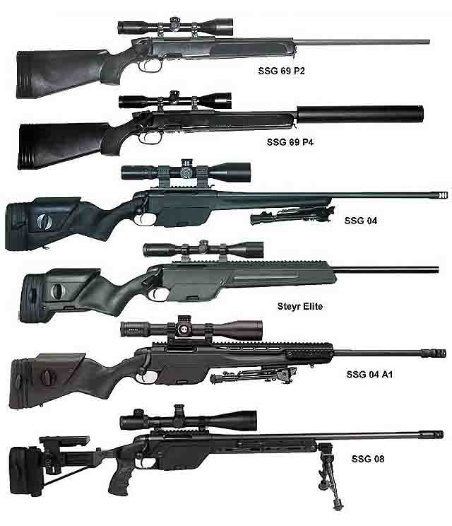
There is an opinion that "Precision" will eventually have to replace the T-5000, as well as foreign high-precision sniper rifles that are in service today, for example, British Accuracy International and Sako TRG, as well as the Austrian Steyr-Mannlicher SSG 04. But, most likely, this sniper complex will complement the "Russian terminator", allowing you to effectively carry out the entire range of tasks facing the Russian special forces.
Watch the video
Tactical and technical characteristics of the sniper rifle "ACCURACY" ORSIS T-5000
ORSIS T-5000(from Russian weapon systems ; also ORSIS T-5000) is a high-precision bolt action sniper rifle. Produced by the weapons factory "ORSIS" of the industrial group "Promtekhnologii", located in Moscow. The rifle was presented in 2011 at the international Russian arms exhibition in Nizhny Tagil. These rifles can be used by both special law enforcement units and specially trained army snipers.
In early June 2012, the team of Directorate "A" of the Central Security Service of the FSB won the international competition of police and army snipers (Eng. Police & military sniper world cup ) using T-5000 rifles. In September 2012, the rifle was tested as part of the Ratnik ground forces equipment kit.
Design sniper rifle
The design of the T-5000 is based on the original bolt group made of stainless steel. The shutter is longitudinally sliding, rotary. The barrel and trigger mechanism of the rifle are also made of stainless steel. The T-5000 is equipped with an ORSIS SE barrel, obtained by a single-pass cutting method. The barrel manufacturing accuracy is about 0.002 mm. Barrel length 27.5 inches (698.5 mm), muzzle diameter - 22 mm. Doles are made on the barrel to reduce the cooling time of the barrel and to reduce the weight of the weapon as a whole. The muzzle of the barrel is threaded for attaching a muzzle brake-compensator or other muzzle devices (equipped with a three-chamber ORSIS muzzle brake-compensator).
Aluminum alloy stock, ergonomic pistol grip, adjustable stock, steel stock folding mechanism with magnetic lock when folded. Depending on the variant of the trigger mechanism, the trigger force can be smoothly adjusted ("Hunter" - allows you to adjust the free travel and effort from 900 to 1500 grams; "Varmint" - from 500 to 900 grams). A three-position safety is made at the rear of the bolt and, if necessary, allows you to manipulate the bolt with the fuse on, or completely block the trigger and bolt. The rifle is equipped with a Picatinny rail for mounting an optical sight and a rail for mounting a pre-objective attachment.
Optical sights for rifles are supplied by Daedalus. Cartridges are fed from detachable box magazines with a capacity of 5 and 10 rounds. Folding stock adjustable in length. On the butt there is a height-adjustable cheek pad.
Purpose and performance characteristics sniper rifle
The performance characteristics of the ORSIS T-5000 rifle allow you to hit targets at any time of the day or night, in any weather conditions, without preliminary adjustment and technical training at distances up to 1650 meters. ORSIS rifles demonstrated accuracy of fire at a level not exceeding 0.5 arc minutes (11 cm at 800 m).
The T-5000 is superior in range and accuracy to the Austrian SSG 08 rifle (purchased for anti-terror and GRU snipers) and the Russian SV-98. The upgraded version of the T-5000M in the future will allow firing at ranges up to 2000 m.
 ORSIS T-5000
There is an opinion...
Sniper complex "Accuracy" hits "abroad"
Dmitry Semizorov, General Director of TsNIITOCHMASH, announced that tests of a sniper rifle with the telling name "Accuracy" for the Russian Ministry of Defense have been postponed to 2017. The situation is rather unusual.
The rifle is not only ready and demonstrates excellent performance, but its version for the Federal Security Service has successfully passed state tests. It is expected that in the near future a government decree will be signed on the adoption of the "Accuracy" by the FSO.
The postponement of the test dates predetermined the fact that the Ministry of Defense requires much more rifles than the FSO.
And therefore, the issue of mass production of weapons is extremely relevant. And here "Accuracy" has a weak point - partly it is made of imported materials . Therefore, the Ministry of Defense was forced to retroactively make changes to the TOR in terms of the manufacturing technology of the product. Since the TK was issued even before anti-Russian sanctions were introduced.
The Tochnost sniper rifle is an atypical product for the domestic defense industry.
Because it is designed and manufactured by the private company Promtekhnologii. The company was registered in Moscow in 2011. And initially it was focused on the manufacture of only civilian products - hunting rifles and sporting rifles. With her weapons, for example, the Russian biathlon team competed at one time. Soon the T-5000 combat sniper rifle was created. All Promtekhnologii weapons are produced under the ORSIS brand. What does "Weapon Systems" mean?
"Promtekhnologii" - a dwarf enterprise
in comparison with such monsters of the arms industry as the Kalashnikov concern, the Tula engineering design bureau, the Kovrov Plant named after. Degtyarev. It employs only 150 people - and designers, and machine operators, and managers. However, the intellectual potential is not limited to the designers of Promtekhnologii alone. The company maintains partnership relations with a number of research institutes and technical universities that conduct scientific research and take part in design work on a contractual basis.
At the very beginning, the post of Deputy General Director of Promtekhnologii was occupied by Alexei Rogozin, the son of the Deputy Prime Minister of Russia for the defense industry. In many ways, this explains the fact that a private company was allowed into the "holy of holies" - among the companies admitted to the struggle for defense orders.
However, under Rogozin Jr., the company only managed to register and "stand on its feet." A year and a half later, he was promoted.
T-5000 belongs to a different class of weapons than SVD
In early 2012, when information appeared that the T-5000 rifle was applying for entry as a sniper weapon into the Russian army, headlines were full of headlines in the most nimble and least competent media: “The Rogozin Jr. rifle will replace the Dragunov sniper rifle in the army.” The fact is that Promtekhnologii also has much more modest ambitions, and the T-5000 belongs to a different class of weapons than the SVD. And there can be no replacement here, even theoretically.
SVD is a mass weapon with automatic reloading.
This rifle has less range and less accuracy. SVD is used by snipers with basic training and low experience. T-500 is a sniper complex for high-precision shooting. This rifle has no automatics, reloading is carried out manually. Due to the fact that precision technologies are used in the manufacture, the weapon has a significantly higher quality. So, when cutting the barrel of a mass weapon, even a sniper, several cuts are made. The barrel of the T-5000 is cut in one pass. There is a certain difference in the quality of the materials used - steel for the barrel and for the mechanisms of the rifle.
There can not be many high-precision weapons in the regular army, and for economic reasons. Because it is very expensive compared to weapons that are massively used in the army. On sale there is a civilian model ORTIS SE T-1500, the cost of which is about 200 thousand rubles.
Combat conditions are different from those that exist in the dash
A number of rifles in 2013 were transferred to the Ministry of Defense for trial operation. As the military comments accumulated, the designers of Promtekhnologii adjusted the weapons. The main comments were made about the "greenhouse" operating conditions. Because the combat conditions are different from those that exist in the dash. At the same time, work was carried out to improve shooting qualities, although there were no comments on this part. As a result, a modernized rifle was born, which was called "Accuracy". It is clear that this is a working name that does not fit into the army tradition of assigning abbreviations to small arms.
If the T-5000 has a firing range of 1650 meters, then for the new model it has been increased to 2000 meters. One of the main advantages is the highest accuracy. The maximum deviation of bullets when firing in the absence of wind for the T-5000 is less than half a minute of arc, which, as you know, is equal to the sixtieth of a degree. That is, with a series of 3-5 shots, all bullets end up in a circle with a diameter of 1.3 centimeters for every 100 meters of distance. Accordingly, at a distance of 1000 meters, the spread will be about 13 centimeters. The modified rifle has even higher accuracy.
The accuracy of shooting is also impressive, which is due to the extremely low tolerances for manufacturing the barrel, the count goes literally to microns. As well as low recoil and minimal effort required for trigger pressure. At the same time, the sight supplied to Promtekhnologii by the Dedal company provides shooting at any time of the day under any weather conditions.
The designers of "Promtekhnologii" adhere to conservative views on the scheme of the rifle. It is a classic bolt-action sniper rifle. The general director of the company, Alexander Fedotov, claims that the classical scheme is far from exhausted and does not require any original innovations. The quality of shooting should be increased through the introduction of new technologies - improving the accuracy of machining, the use of materials of the highest quality. At the same time, several machines used in the manufacture of weapons are independently created by the company. These include, for example, a machine for cutting a barrel.
Of course, at the same time, in order to facilitate the work of a sniper, the weapon must be individualized as much as possible - that is, it must be given the opportunity to “customize” it to the shooter.
The ORTIS rifle has many adjustments both in geometry and in the forces applied by the sniper.
The rifle is designed for three different cartridges: 7.62x51mm (.308 Winchester), 7.62x67mm (.300 Winchester Magnum) and 8.6x70mm (.338 Lapua Magnum). Barrel length depending on the cartridge used: 508/671/698.5 mm. The length of the rifle in the unfolded state: 1270/1060/1230 mm. Weight: 6.1/6.3/6.5 kg. Shop for 5 and 10 rounds. Data on the upgraded rifle, called "Accuracy", is not reported. But, of course, if they differ, it will be insignificant.
The T-5000 has already shown itself in the sniper business. With her help, Russian teams of snipers from various law enforcement agencies won international competitions.
If the new rifle is put into service, it will replace not the SVD, but a weapon similar in purpose and capabilities
In particular, under the guns of "Promtekhnologii" - Steyr-Mannlicher SSG-08 sniper rifles purchased in Austria with a manual reloading longitudinally sliding bolt with a NATO cartridge of 7.62 × 51 mm. This rifle has a worse range and accuracy than the T-5000. Also in the special forces of the Ministry of Internal Affairs and the FSB, the Finnish sniper rifle Sako TRG-22 was "registered", which, with an excess of performance, will be replaced by "Accuracy".

Sako TRG sniper rifle
 Steyr-Mannlicher SSG sniper rifle of various modifications
 According to experts, the T-5000 is not inferior to the best foreign models, but in some ways it significantly surpasses them.
Thus, the British company Accuracy International, which is considered a trendsetter in sniper fashion, produces a rifle of the same design with a bolt-action L96A1, which has a maximum firing range with the most powerful cartridge of 1500 meters. At the same time, the accuracy of 7.62 mm cartridges is excellent - 0.4 arc minutes. But with powerful cartridges, it increases to 0.7 minutes. The T-5000 has 0.5 minutes. But at the same time, a British rifle costs much more - from 12 to 20 thousand dollars, depending on the modification.
And in conclusion, it is necessary to explain why the general director of NIITOCHMASH comments on the situation with the "foreign" rifle. The fact is that NIITOCHMASH is the lead developer of the Ratnik military equipment. In addition to the suit, body armor, shoes, the equipment also includes various technical devices, as well as various types of weapons. Moreover, this is not only an individual weapon, but also an “elite” one, individually outstanding for large units.
2018-09-27T07:57:26+05:00 kreg_74Defense of the Fatherlandarmy, weapons, watch videos, special forces, special servicesSniper rifle "Tochnost" for anti-terror groups, FSB and FSOS The sniper rifles developed as part of the development work "Tochnost" are ready for serial deliveries. This, according to TASS, was announced by the head of the Central Research Institute of Precision Engineering (TsNIITOCHMASH) Dmitry Semizorov. “The rifles passed the state tests successfully. The work of the interdepartmental commission has already been completed, letters have already been assigned, ”Semizorov said, ...kreg_74 Evgeny Krasnoperov kreg_74 [email protected] Author In the middle of RussiaFirst of all, it must be said that the base sample is a sniper rifle designed by E.F. Dragunova - in its class of self-loading sniper weapons in terms of the generalized parameter of accuracy of fire, the reliability of automation in difficult operating conditions, the simplicity of the device and low weight, is the best in the world. Undoubtedly, it is possible to develop a self-loading sniper rifle with a higher accuracy of fire (for example, the SR-25 sniper rifle), but achieving the same reliability of automation as that of the SVD in different climatic conditions is very doubtful. When developing Russian weapons, reliability has always been given paramount attention.
Despite all the positive qualities of the SVD, until recently, it did not meet the requirements of the airborne troops for such an important technical parameter as the overall length of the rifle. A sniper parachuting loaded with equipment was not able to carry a long sniper rifle, due to the danger of being injured or even killed on landing. Therefore, after landing, the sniper had to look for his weapon, which was landed separately.
It was impossible to put up with such a state of affairs in such highly mobile troops, and the Main Artillery Directorate (GAU) initiated development work to modernize the Dragunov sniper rifle in order to reduce the linear dimensions of the weapon.
The creator of the SVD himself, Evgeny Fedorovich Dragunov, was well aware that the SVD should be more maneuverable. The design bureau team developed various versions of the SVD, including those made according to the bullpup scheme. A characteristic feature of the bullpup is compactness, but the barrel shifted deep into the stock and the receiver and magazine placed behind the trigger mechanism lead to the appearance of those shortcomings that are unacceptable to put up with in sniper weapons. This arrangement of weapons, by the way, has never been approved by the US armed forces. And only here in Russia, such a respected company as TsKIB SOO disfigures the SVD into a bullpup, while violating the copyrights of the developers.
As a result of a long search, all "exotic" options were rejected. Work on the modernization of the SVD rifle was carried out at the Izhmash production association simultaneously by two design teams. In the honest and stubborn struggle of the designers of one weapons school, a new weapon was born.
 |
SIDS acquired new features compared to SVD, but remained no less beautiful and graceful |
 |
The SVDS stock is folded onto the right side of the receiver Thus, when folding the butt, there is no need for department of the optical sight. Placement becomes more comfortable rifles in the packing of a paratrooper during landing. cheek support has can be fixed in two positions - for firing from mechanical sighting device and optical sight |
When the task is formulated clearly enough, it is necessary not to make a mistake in determining the ways to solve it. As a result of the work carried out, it became clear that the required length of the rifle in the stowed position can be obtained by slightly reducing the length of the barrel, using a folding butt and a compact flash hider. At this stage, the task arose - how to maintain the accuracy of shooting from a rifle when changing its individual elements? A number of important issues needed to be addressed. Among them: reducing the length of the barrel with an increase in its rigidity due to an increase in the outer diameter; development of a flame arrester of shorter length, but with the preservation of the efficiency of flame suppression when fired and providing parameters for the level of sound exposure to the shooter within the limits of a standard flame arrester; folding stock design.
The greatest difficulty among the above works was the development of a folding stock with a rigidity comparable to that of a stock stock. It is known that any movable connection of two parts implies the presence of gaps in them and, accordingly, a decrease in the rigidity of the connection. The slight movement of parts and parts of the weapon that occurs at the moment of the shot from the action of recoil forces leads to a change in the average point of impact and, ultimately, to a loss of accuracy.
After working out several layout schemes, a variant of the butt mount with a vertical hinge axis and a horizontal position of the butt lock was chosen. The buttstock is folded to the right side of the receiver, which is more convenient for bringing the buttstock into combat position in comparison with the AK74M assault rifle. The butt is made of steel pipes with a butt plate and cheek rest made of polyamide. The cheek rest is mounted on the top tube of the buttstock and can be rotated on it with the possibility of fixation in 2 positions: the upper one - when firing using an optical sight and the lower one - when firing using a mechanical sight.
To accommodate the attachment points for the butt and the pistol grip, the receiver of the SVDS in comparison with the SVD rifle in the rear is modified. The trigger housing and the trigger hook have undergone minor changes.
To simplify the maintenance of the rifle in a combat situation, the operating mode of the gas outlet device was optimized, which made it possible to exclude the gas engine regulator from the design.
The research work carried out on the search and development of the design of a flame arrester with small linear dimensions led to the choice of an option that is not inferior to a regular flame arrester both in terms of the degree of flame suppression and in terms of the level of sound pressure on the shooter's hearing organs.
The SVDS sniper rifle passed a full range of factory, field and flight tests and was adopted by the Russian army. The knowledge acquired during the creation of the rifle made it possible to successfully solve the problems of developing hunting weapons. Later, a variant of a quick-detachable butt was created, which allows you to significantly reduce the dimensions of hunting weapons during transportation and storage.
Now the Dragunov sniper rifle with the prefix "C" has no worthy rivals in the world market and in terms of weight and dimensions.
| Tactical and technical characteristics of rifles SVD and SVDS | ||
| performance characteristics | SVD | |
| Caliber, mm | 7,62 | 7,62 |
| Applicable cartridge | 7.62x53 | 7.62x53 |
| Combat rate of fire, rds / min | 30 | 30 |
| Range to which the lethal effect of the bullet is maintained, m | 3800 | 3800 |
| Muzzle velocity, m/s | 830 | 810 |
| Sighting range, m: | ||
| - with open sight | 1200 | 1200 |
| - with optical sight | 1300 | 1300 |
| Barrel length, mm | 620 | 565 |
| Guaranteed barrel survivability, rds. | 10 000 | 10 000 |
| Magazine capacity, cartridges | 10 | 10 |
| Number of grooves | 4 | 4 |
| Rifle length with bayonet, mm | 1370 | - |
| Rifle dimensions without bayonet, mm: | ||
| - length with folded butt | 1220 | 1135 |
| - length with folded butt | - | 875 |
| - height | 230 | 175 |
| - width | 88 | 88 |
| The mass of a rifle without a bayonet-knife with an optical sight, an unloaded magazine and a cheek, kg | 4,30 | 4,68 |
| Type of main sight | optical, PSO-1M | |
| Optical sight magnification, fold. | 4 | 4 |
Vladimir Simonenko
INTRODUCTION
The technical description and operating instructions for the 7.62-mm Dragunov sniper rifle (SVD) are designed to study rifles and optical sights and maintain them in constant combat readiness.
This document contains technical specifications and information about the design and principle of operation of a rifle and an optical sight, as well as the basic rules necessary to ensure the correct operation of a rifle with a sight and the full use of their technical capabilities.
|
https://igratnadengi.org |
1.TECHNICAL DESCRIPTION
1.1. The purpose of the rifle
1.1.1. The 7.62 mm Dragunov sniper rifle (index 6V1) is a sniper's weapon and is designed to destroy various emerging, moving, open and camouflaged single targets (Fig. 1).
Optical sniper sight (index 6Ts1) is used for precise aiming from a sniper rifle at various targets.
Rice. 1. 7.62 mm Dragunov sniper rifle with optical sight and bayonet:
1 - 7.62 mm Dragunov 6V1 sniper rifle. Sat.;
2 - sniper optical sight 6Ts1. ALZ. 812.000;
3 - bayonet-knife assembly 6x5 sb
1.1.2. For firing from a sniper rifle, rifle cartridges with ordinary, tracer and armor-piercing incendiary bullets, as well as sniper cartridges are used. The sniper rifle fires single shots.
1.1.3. The optical sight allows you to fire at night at infrared sources, as well as under adverse lighting conditions, when it is difficult to shoot at targets with an open sight.
When observing infrared sources, the infrared rays emitted by the source pass through the lens of the sight and act on the screen located in the focal plane of the lens. At the site of action of infrared rays, a glow appears on the screen, giving a visible image of the source in the form of a round greenish spot.
1.2. Technical data
1.2.1. The main design ballistic characteristics of the rifle, rifle cartridge and the design data of the optical sight are given in Table. one.
Table 1
1. Caliber, mm 7.62
2. Number of grooves 4
3. Sighting range, m:
with telescopic sight 1300
open sight 1200
4. Muzzle velocity, m/s 830
5. Range of the bullet, up to which its lethal effect is maintained, m 3800
6. The mass of the rifle without a bayonet-knife with an optical sight, unloaded
store and cheek, kg 4.3
7. Magazine capacity, rounds 10
8. Rifle length, mm:
without bayonet 1220
with attached bayonet 1370
9. Cartridge mass, g 21.8
10. Mass of an ordinary bullet with a steel core, g 9.6
11. Weight of powder charge, g 3.1
12. Increase in the optical sight, fold. 4
13. Field of view of the sight, degree 6
14. Exit pupil diameter, mm 6
15. Exit pupil removal, mm 68.2
16. Resolution, second, 12
17. The length of the sight with an eyecup and extended hood, mm 375
18. Sight width, mm 70
19. Sight height, mm 132
20. Weight of the sight, g 616
21. Weight of the sight with a set of spare parts and accessories and a case, g 926
1.3. Composition of the rifle
1.3.1. The sniper rifle kit includes (Fig. 1):
optical sniper sight, index 6Ts1 - 1 pc.;
bayonet-knife, index 6X5 - 1 pc.;
bag for sight and magazines (Fig. 3), index 6Sh18 - 1 pc.;
bag for spare parts (Fig. 4), index 6Sh26 - 1 pc.;
belt for carrying small arms (Fig. 5), index 6Sh5 - 1 pc.
1.3.2. The sniper optical sight is completed with a cover, a winter lighting system and an individual spare parts kit.
1.4. The device and operation of the rifle

Rice. 2. 7.62 mm Dragunov sniper rifle:
1- frame 6B1. 2-7; 2- drummer 6V1 2-5; 3- cover 6V1. Sat. 5; 4- rod guide 6B1. 5-6; 5- bushing guide 6B1. 5-5; 6- shutter 6B1. 2-1; 7- axis of the ejector 6V1. 2-3; 8- pin of the drummer 6V1. 2-6; 9- ejector spring 6V1. 2-4; 10 - ejector 6V1. 2-2; 11- return spring 6V1. 5-4; 12- clamp of the aiming rail 6V1. 48; 13- aiming rail 6V1. 1-21; 14- lining left assembly 6В1. Sat. 1-3; 15- pusher spring 6V1. 1-24; 16- latch of the gas pipe 6V1. 1-38; 17- gas chamber 6V1. 1-15; 18- gas piston 6V1. 1-22; 19 - gas pipe 6V1. 1-25; 20- gas regulator 6V1. 1-53; 21- front sight body 6V1. 1-20; 22 - front sight 6V1. 1-17; 23- pusher 6V1. 1-23; 24 - front sight base 6B1. 1-16; 25-barrel 6V1. 1-1; 26- upper ring assembly 6V1. Sat. 1-1; 27- check of the ring 6Bl. Sat. 1-7; 28- stuffing box assembly 6V1. Sat. 1-8; 29- right overlay assembly 6В1. Sat. 1-4; 30- lower ring with spring 6V1. Sat. 1-5; 31- store case 6V1. Sat. 6-1; 32- magazine spring 6V1. 6-12; 33- store cover 6V1. 6-11; 34- bar assembly 6B1. Sat. 6-3; 35- feeder 6V1. Sat. 6-2; 36- box 6B1. 1-2; 37-shield assembly 6V1. Sat. 3; 38 - trigger mechanism 6V1. Sat. 4; 39 - cover pin 6B1. Sat. 1-2; 40 - butt 6V1. Sat. 7
1.4.1. The sniper rifle has the following main parts and mechanisms (Fig. 2):
trunk with a box;
shutter with frame;
shield assembly;
trigger mechanism;
cover with a return mechanism;
score;
butt;
top ring assembly;
overlay left assy;
lining right assembly;
aiming bar assembly;
the base and body of the fly assembly.
1.4.2. The sniper rifle is a self-loading weapon. Reloading a rifle is based on the use of the energy of powder gases discharged from the bore to the gas piston.
When fired, part of the powder gases following the bullet rushes through the gas outlet in the barrel wall into the gas chamber, presses on the front wall of the gas piston and throws the piston with the pusher, and with them the frame to the rear position.
When the frame moves back, the bolt opens the bore, removes the sleeve from the chamber and throws it out of the receiver, and the frame compresses the return springs and cocks the trigger (sets it to cock the self-timer).
The frame with the bolt returns to the forward position under the action of the return mechanism, while the bolt sends the next cartridge from the magazine to the chamber and closes the barrel bore, and the frame brings the self-timer sear out from under the self-timer platoon of the trigger and the trigger becomes cocked. The shutter is locked by turning it to the left and entering the lugs of the shutter into the cutouts of the receiver.

Rice. 3. Bag for sight and magazines 6Sh18. Sat.

Rice. 4. Bag for spare parts and accessories 6Sh26. Sat.

Rice. 5. Belt for carrying small arms 6Sh5. Sat.

Scope case
To fire another shot, release the trigger and pull it again. After the trigger is released, the rod moves forward and its hook jumps over the sear, and when the trigger is pressed, the rod hook turns the sear and disconnects it from the cocking of the trigger. The trigger, turning on its axis under the action of the mainspring, strikes the striker, and the latter moves forward and pricks the primer-igniter of the cartridge. There is a shot.
When the last cartridge is fired, when the bolt moves back, the magazine feeder raises the bolt stop, the bolt rests against it and the frame stops in the rear position. This is the signal to reload the rifle.
The rifle has a gas regulator that changes the rollback speed of moving parts.
Under normal operating conditions, with lubricated parts, the regulator is set to division 1. During prolonged shooting without cleaning and lubrication and heavy contamination of the rifle, a delay may occur - incomplete withdrawal of moving parts. In this case, the regulator is switched to setting 2. The regulator is transferred from one position to another using the sleeve flange or cartridge.
1.5. The device and operation of the sight and its components
1.5.1. Sniper optical sight (Fig. 6) has the following main parts:
frame;
lens;
eyepiece;
hood;
eyecup;
handwheel with a scale of aiming angles;
handwheel with a scale of lateral corrections;
handle;
light filter in the frame;
guide;
source of power;
lamp;
cap.
A lens in a frame with a retractable hood is screwed into the body, and an eyepiece assembly with an eyecup is screwed into the other end of the body. On top of the body is a handwheel with a scale of aiming angles, printed on its cylindrical part. On the handwheel nut are the inscriptions "Up", "Down", "STP" and arrows showing the direction of rotation of the handwheel when aligning the sight.
The aiming angle scale has ten divisions (from 0 to 10). The division price is 100 m. Starting from division 3, using the latch available in the handwheel, it is possible to set aiming angles after 50 m.
On the right side of the case there is a handwheel with a scale of lateral corrections, on the cylindrical part of which 21 divisions are applied (from 0 to 10 in both directions). The dashes and numbers to the right of 0 are black, those to the left of 0 are red.
The scale division value is 0-01. Using the latch located in the handwheel, you can set the corrections through O-00, 5. On the nut securing the handwheel of the lateral correction mechanism, the inscriptions -Right-, -Left-, -STP- and arrows showing the direction of rotation when aligning the sight are applied.

Rice. 6. Appearance of the sight PSO-1:
1 - blend AL7. 006.002; 2 - lens in frame AL5.917.001; 3 - light filter in frame AL5.940.003; 4- handle AL8.333.004; 5- nut AL8.373.004; 6- handwheel AL8.330.007; 7- case AL8.020.016; 8- eyepiece assembly AL5.923.010; 9- eyecup AL8.647.030; 10 - cap AL6.628.000; 11 - cap AL8.634.003.
On the belts of the handwheel of the aiming angles and the handwheel of the lateral corrections, 60 divisions are applied. The division value is 0-00, 5. The divisions on the handwheel belts serve to read off the correction when aligning the sight on the rifle.
The backlight power supply is located in the housing socket. The nest is closed with a cap.
1.5.2. The optical system of the sight is designed to build an image of objects located on the ground and is a monocular telescopic system with constant magnification.
The optical system (Fig. 7) consists of objective lenses, a reticle, an inverting system, eyepiece lenses, a screen, a light filter, a light orange light filter, and protective glass.
The lens is designed to build an image of the observed object. The image of objects in the focal plane of the lens is inverted from left to right and from top to bottom.
The inverting system is designed to produce a true straight image.
The eyepiece is used to view the image of the observed object and the grid.
The light orange light filter is designed to improve the work with the sight in cloudy weather to increase the contrast of the image.

Rice. 7. Optical scheme:
1,2,3 - AL7 objective lenses. 504.012, AL7.563.006, AL7.523.003; 4 - welded screen 51-IK-071 Sat.14 5,6,7,8 - lenses AL7.504.013, AL7.563.007, AL7.563.008, AL7.504.014 (turning system); 9 - grid AL7.210.009; 10,11,12 - eyepiece lenses AL7.546.001, AL7.508.004, AL7.508.005; 13 - light orange light filter AL7.220.005; 14 - light filter AL7.220 006; 15 - protective glass AL8.640.004.
The grid is a plane-parallel plate. On the plate there are scales for aiming angles and lateral corrections, as well as a rangefinder scale. The view of the field of view of the sight is shown in Figure 8. The aiming angle scale is made in the form of squares up to a range of 1300 m. When the aiming angle handwheel scale is set to division 10, the top of the second aiming sign from the top of the scale on the grid will correspond to a range of 1100 m, the top of the third sign - 1200 m , and the top of the fourth - 1300 m. 
Rice. 8. Kind of field of view
To the left and right of the sighting signs is a scale of lateral corrections. Scale division value 0-01. The values of lateral corrections 0-05 and 0-10 are marked with an elongated stroke. Amendment O-10 is marked with the number 10. Two horizontal strokes are applied to the right and left of the scale of lateral corrections.
The rangefinder scale, located on the left under the lateral correction scale, is designed to determine the range to the target. The rangefinder scale is made in the form of two lines. The upper line (curve) is calculated for a target height of 1.7 m and is marked with the numbers 2, 4, 6, 8 and 10.
The sight reticle moves in two mutually perpendicular directions, always remaining in the focal plane of the lens.
1.6. Rifle affiliation
1.6.1. The accessory (fig. 9) is used for disassembling, assembling, cleaning and lubricating the sniper rifle and is carried in a bag for the scope and magazines.
1.6.2. Accessories include: cheek, ramrod, rubbing, ruff, screwdriver, punch, pencil case and oiler.
The cheek is used when shooting from a rifle with an optical sight. In this case, it is put on the butt of the rifle and fixed on it with a lock.
The ramrod is used for cleaning and lubricating the bore, channels and cavities of other parts of the rifle. It consists of three links screwed together.
Wiping is designed to clean and lubricate the bore, as well as the channels and cavities of other parts of the rifle.
The ruff is used to clean the bore with RFS solution.
A screwdriver is used when disassembling and assembling a rifle, cleaning the gas chamber and gas tube, and also as a key when adjusting the position of the front sight in height.
A punch is used to push out axles and pins.
The case serves for storage of rubbing, a ruff, a screw-driver and a punch. It consists of two components: a key case and a case cover.
The key case is used as a ramrod handle when cleaning and lubricating a rifle, as a screwdriver handle when disassembling and assembling a rifle, and as a key when separating a gas tube and assembling a ramrod.
The case cover is used as a muzzle pad when cleaning the barrel.
The lubricator is used to store the lubricant.

Rice. 9. Rifle affiliation:
1- case cover 6Yu7. 1-6; 2- ruff 56-Yu-212. Sat. 5; 3- screwdriver 6Yu7. one; 4- wiping 56-U-212. Sat. 4; 5- drift 56-Yu-212. 5: 6 - case of the case 6Yu7. Sat. 1-1; 7- oiler 6Yu5. Sat. Sat; 8 - cheek 6Yu7. Sat. 6; 9- ramrod 6Yu7. 2-1; 10- ramrod extension 6Yu7. 2-2; 11- front ramrod extension 6Yu7. 2-3
1.7. Scope accessory
1.7.1. The accessory (Fig. 10) is designed to ensure the normal operation of the sight and replace individual elements that have failed during operation.
1.7.2. Accessories include: a cover, a winter lighting system, a light filter in a frame, a key. cloth, lamp power supply (cassette) and cap.

Rice. 10 Appearance of the PSO-1 sight with an individual set of spare parts and accessories:
1- key AL8. 392.000; 2- section of mercury-zinc elements 2RTs63; 3 - light filter AL5.940.004; 4 - lamp CM 2.5-0.075 (in cassette AL8.212.000); 5- cap AL8.634.004; b- lighting system AL6.622.004
The cover serves to protect the sight from dust, rain, snow, exposure to sunlight, etc.
The winter lighting system is designed to provide illumination of the sight reticle when working with the sight at an ambient temperature below 0°C. WITH.
The light filter in the frame is used to work with the sight in cloudy weather.
The wrench is used to screw in and unscrew the reticle illumination lamp.
The cloth is used for cleaning optical parts. The power supply, lamps and cap are designed to replace failed ones.
1.8. Container and packaging
1.8.1. The consumer receives sniper rifles in wooden boxes painted in a protective color. Six sniper rifles with all accessories are placed in each box and secured with special inserts.
1.8.2. The box consists of two compartments separated by a wooden partition. The bottom, as well as all the walls of the box, are lined with paraffin paper. Before capping, the bottom and walls of the large compartment of the box are additionally lined with inhibited paper. The small compartment of the box is not lined with inhibited paper, and the optical sights and belts for carrying small arms sealed in this compartment are wrapped only with paraffin paper.
2. INSTRUCTIONS FOR USE
2.1. General instructions
The sniper rifle and optical sight must be kept in perfect working order and ready for action. This is achieved by timely and skillful cleaning and lubrication, careful attitude, proper storage, timely technical inspections and elimination of detected malfunctions.
2.2. Safety Instructions
2.2.1. Training in disassembling and assembling a rifle should be carried out only on training rifles. Training on combat rifles is permitted only in exceptional cases, with special care in handling parts and mechanisms.
2.2.2. Before preparing the rifle for shooting, and before cleaning and lubricating, make sure that it is not loaded.
During all training activities with a loaded rifle, do not point it at people or in the direction where people and pets may be.
Shoot in a closed shooting range only if there is a supply and exhaust ventilation, since the powder gases emitted during firing are toxic. At the end of the shooting, be sure to unload the rifle and put it on the safety.
2.3. Preparing a sniper rifle and an optical sight for shooting
2.3.1. Preparing the rifle and the scope for firing is designed to ensure that they work smoothly while firing. Preparation of a rifle and a sight for shooting is carried out in the following order:
a) clean the rifle;
b) inspect the disassembled rifle and lubricate it;
c) inspect the assembled rifle and scope;
d) check the correct interaction of parts and mechanisms of the rifle;
e) check the serviceability of the lighting system and grid illumination;
f) check the operation of the aiming angles and lateral adjustments of the sight;
g) check the screen on and off;
h) charge the screen of the sight.
Immediately before shooting, wipe dry the bore (rifled part and chamber), inspect the cartridges and equip the magazine with them.
To charge the sight screen, rotate the screen switch knob to the position along the sight, place the sight so that the entire surface of the filter is illuminated by a light source containing ultraviolet rays.
Full charge time: in daylight diffused light - 15 minutes, when illuminated by direct sunlight and when irradiated with an electric lamp with a power of 100 ... 200 W at a distance of 20 cm - 7-10 minutes. Charging the screen beyond the specified time does not increase its sensitivity. A charged screen retains the ability to capture infrared rays for 6 ... 7 days, after which it must be charged again. Charging ensures the operation of the sight for 3 days (when working 8 hours a day).
2. 4. Bringing the rifle to normal combat and the procedure for working with an optical sight
2.4.1. The sniper rifle in the unit must be brought into normal combat. The need to bring the rifle into normal combat is established by a combat check.
Rifle combat is checked:
a) upon receipt of a rifle in the unit;
b) after repairing the rifle and replacing parts that could change its action;
c) upon detection during firing of deviations of the midpoint of impact (STP) or dispersion of bullets that do not meet the requirements of normal rifle combat.
In a combat situation, a check of the combat of a rifle is carried out periodically at every opportunity.
2.4.2. To test the fight, fire four shots, carefully and uniformly aiming through the open sight. Shoot at a black rectangle measuring 20 cm in width and 30 cm in height, mounted on a white shield 0.5 m wide and 1 m high. The aiming point is the middle of the lower edge of the black rectangle. On a plumb line at a distance of 16 cm above the aiming point, mark with chalk or colored pencil the normal position of the midpoint of impact when firing with an open sight. This point is the control point (CT).
Firing range 100 m, sight 3. Position for firing "lying from the stop". To check the battle of a rifle and bring it to normal combat, cartridges with an ordinary bullet with a steel core are used. Shoot without a bayonet-knife.
At the end of the shooting, inspect the target and the location of the holes, determine the accuracy of the battle and the position of the midpoint of impact.
The accuracy of a rifle battle is considered normal if all four holes fit into a circle with a diameter of 8 cm.
If the accuracy of the location of the holes does not meet this requirement, repeat the shooting. In case of repeated unsatisfactory shooting results, send the rifle to a repair shop.
If the grouping of the battle is normal, determine the mid-point of impact and its position relative to the control point. The definition of the midpoint of impact is shown in fig. eleven.

Rice. 11. Determination of the midpoint of impact:
1 - sequential division of segments; 2 - with a symmetrical arrangement of holes.
A rifle fight is considered normal if the average point of impact coincides with the control point or deviates from it in any direction by no more than 5 cm.
2.4.3. If, when checking the battle, the middle point of impact deviated from the control point in any direction by more than 5 cm, then change the position of the front sight in height or the body of the front sight in lateral position. If the STP is below CT, then screw in the front sight, if it is higher, unscrew it. If the STP is to the left of the CT, move the body of the front sight to the left, if to the right - to the right.
When moving the body of the front sight to the side by 1 mm, when screwing in (unscrewing) the front sight for one full turn, the STP shifts by 16 cm when shooting at 100 m.
Check the correctness of the movement of the body of the front sight and the front sight by repeated shooting. After bringing the rifle to normal combat, drive in the old risk on the body of the front sight, and apply a new one instead.
2.4.4. To bring the rifle into normal combat with a telescopic sight, attach a scope to the rifle and put the cheek on the stock. Turn the handwheels to set the aiming angles handwheel to 3 divisions, and the lateral corrections handwheel to 0 division.
Shoot with an optical sight under the same conditions as when checking the battle of a rifle with an open sight, only mark the control point at a height of 14 cm from the aiming point. If, as a result of shooting, all four holes fit into a circle with a diameter of 8 cm, but the STP deviated from the CT by more than 3 cm, determine the deviation of the STP and make the appropriate corrections in setting the nuts on the aiming angle and lateral corrections handwheels. Moving the nuts by one division relative to the scale on the handwheel belt when shooting at 100 m changes the position of the STP by 5 cm. them to the required size and tighten the screws.
After making adjustments to the settings of the handwheels, fire again. If, during repeated firing, all four holes fit into a circle with a diameter of 8 cm, and the STP coincided with the CT or deviated from it in any direction by no more than 3 cm, then the rifle is considered to be brought to normal combat. Upon completion of bringing the rifle to normal combat, enter the position of the STP in the form.
2.4.5. Determining the range to the target is carried out in the following sequence:
— align the target image with the rangefinder scale of the reticle so that the base of the target is on the horizontal line of the rangefinder scale, and the top point of the target touches the upper (dotted) line of the scale without a gap;
- take a reading on the rangefinder scale at the point of contact with the target;
- the number indicating the point of contact will determine the distance to the target (in Fig. 12, the distance to the target is 400 m).

Rice. 12. Rangefinder scale
2.4.6. For shooting at dusk and at night, turn the micro-tumbler handle to the -ON- position. In this case, set aiming angles and lateral corrections by counting the clicks of the latch from the zero position. At the same time, remember that the fixation of the aiming angle handwheel from 0 to 3 occurs through an integer division, i.e. after 100 m, and then until setting 10 every half division, i.e. after 50 m. through 0-00, 5.
2.4.7. When working with a winter lighting system, the body with section 2РЦ63 must be stored in a warm place (in the pocket of a tunic or sniper's overcoat).
2.5. Checking the technical condition, typical malfunctions and methods for their elimination
2.5.1. To check the serviceability of the rifle, as well as to determine its suitability for further use, carry out periodic inspections of the rifle.
When inspecting, make sure that all parts of the rifle are present and check that the outer parts are free of rust, dirt, dents, scratches, nicks, chips and other damage that could cause malfunction of the rifle and optical sight mechanisms; in addition, check the condition of the lubricant on the parts visible without disassembling the rifle, the presence of magazines, a bayonet, accessories, a cover for an optical sight, a bag for a sight and magazines and a bag for spare parts; make sure that there are no foreign objects in the bore; check the correct operation of parts and mechanisms.
When checking the correct operation of parts and mechanisms, remove the safety lock, pull the frame by the handle back to failure and release it; the frame should stop in the rear position by stopping the shutter. Separate the store, pull the frame back by the handle a little and release it; the frame should vigorously return to the forward position.
Put the rifle on the safety and pull the trigger; the trigger should not fully retract, and the hammer should remain cocked. Remove the safety from the rifle and pull the trigger: a click should be heard - an energetic blow of the hammer on the firing pin. Put the rifle on the safety again and attach the magazine; the frame should not move back; fuse must be securely held in position.
Check the supply of cartridges to the chamber; extraction and reflection of shells (cartridges); equip the magazine with training cartridges, attach it to the rifle and, without pressing the magazine latch, try to separate the magazine with your hand; the magazine should freely enter the receiver window and be securely held by the magazine latch. Reload the rifle several times, while training cartridges should be sent without delay from the magazine to the chamber and vigorously thrown out of the receiver out.
When checking the serviceability of the optical sight, make sure that the eyepiece and objective lenses are intact, check the smooth rotation of the handwheels and their fixation in the installed position, if there is any pitching of the handwheels, if there is any pitching of the sight, and whether it is securely fixed with a clamping screw on the rifle; check the correctness of the grid lighting; why put a cap on the lens, turn on the toggle switch and look into the eyepiece (with a working device, the grid is clearly visible, if the grid is not visible, replace the battery or light bulb).
If the scope wobbles or the knob does not fit into the cutout on the bracket when the scope is firmly attached to the rifle, adjust the clamping screw. To do this, separate the sight from the rifle, press the slider against the handle (compress the spring) and screw or unscrew the adjusting nut of the clamping screw.
Check your ammo before firing. Check them on inspection. whether there are rust and bruises on the cases, whether the bullet staggers in the muzzle of the case, whether there is a green coating and cracks on the primer, whether the primer protrudes above the surface of the bottom of the case, whether there are training cartridges among the combat cartridges. Return all defective cartridges to the warehouse.
2.5.2. Troubleshoot rifle, optical sight, magazines and accessories immediately. If the malfunctions cannot be eliminated in the unit, send the rifle (optical sight, magazines, accessories) to a repair shop.
2.5.3. Parts and mechanisms of a sniper rifle, with proper handling of the rifle and proper care for it for a long time, work reliably and without fail. However, as a result of contamination of the mechanisms, wear of parts and careless handling of the rifle, as well as malfunctioning cartridges, delays in firing can occur.
Eliminate the delay that occurred during shooting by reloading, for which quickly pull the frame back by the handle, release it and continue shooting. If the delay persists, find the cause of the delay and correct the delay as shown in Table 2.
table 2
| Name of the malfunction, external manifestation and additional signs | Probable Cause | Elimination method |
| Cartridge failure, bolt in the forward position, but no shot was fired - there is no cartridge in the chamber | 1. Contamination or malfunction of the magazine 2. Malfunction of the magazine latch | If the delay repeats, replace the magazine If the magazine latch is faulty, send the rifle to a repair shop |
| Sticking a cartridge. The bullet bullet hit the breech section of the barrel, the moving parts stopped in the middle position | The curvature of the bends of the side walls of the store | While holding the frame handle, remove the stuck cartridge and continue shooting. If the delay repeats, replace the magazine |
| Misfire. The bolt is in the forward position, the cartridge is in the chamber, the trigger is pulled - the shot did not occur | 1. Chuck failure 2. Malfunction of the drummer or trigger mechanism; grease contamination or hardening | Reload your rifle and keep shooting When repeating the delay, inspect and clean the firing pin and firing mechanism; if they break or wear out, send the rifle to a repair shop |
| Non-removal of the sleeve. The cartridge case is in the chamber, the next cartridge was buried in it with a bullet, the moving parts stopped in the middle position | 1. Dirty cartridge or dirty chamber 2. Contamination or malfunction of the ejector or its spring | Pull the frame back by the handle and, holding it in the rear position, separate the magazine and remove the stuck cartridge. Remove the cartridge case from the chamber with a bolt or ramrod Keep shooting. When repeating the delay, clean the chamber. Inspect and clean the ejector from dirt and continue shooting |
| Sticking or non-reflection of the sleeve. The sleeve was not ejected from the receiver, but remained in it in front of the bolt or sent back to the chamber by the bolt | 1. Contamination of rubbing parts, gas paths or chamber 2. Contamination or malfunction of the ejector Pull the frame back by the handle, eject the cartridge case and continue shooting. When repeating the delay, clean the gas paths, rubbing parts and the chamber | If the ejector malfunctions, send the rifle to a repair shop |
2.6. Disassembly and assembly of the rifle
2.6.1. Disassembly of a sniper rifle can be incomplete and complete: incomplete - for cleaning, lubricating and inspecting the rifle; full - for cleaning when the rifle is very dirty, after being in the rain or in the snow, when switching to a new lubricant and during repairs. Frequent disassembly of the rifle is not allowed, as this accelerates the wear of parts and mechanisms.
When disassembling and assembling the rifle, do not use excessive force and sharp blows.
When assembling. rifle, compare the numbers on its parts with the number on the receiver.
2.6.2. The order of incomplete disassembly of a sniper rifle:
a) separate the store. Taking the magazine with your hand, press the magazine latch and, while feeding the bottom of the magazine forward, separate it. After that, check if there is a cartridge in the chamber, for which lower the fuse down, pull the frame back by the handle, inspect the chamber and lower the handle;
b) separate the optical sight. Raising the handle of the clamping screw, turn it towards the eyecup until it stops, move the sight back and separate it from the receiver;
c) separate the cheek. Turning the cheek lock latch down, remove the loop from the clip hook and separate the cheek;
d) separate the cover of the receiver with a return mechanism. Turning the pin of the cover back until it is placed on the screw-limiter of the checks, lift up the back of the cover and separate the cover with the return mechanism;
e) separate the frame with the shutter. Pulling the frame with the bolt back to failure, lift it and separate it from the receiver;
f) separate the shutter from the frame. Pulling the shutter back, turn it so that the leading ledge of the shutter comes out of the figured groove of the frame, and then move the shutter forward;
g) separate the trigger mechanism. Turning the shield up to a vertical position, slide it to the right and separate it from the receiver; holding the bracket, move down to separate the firing mechanism;
h) separate the barrel linings. Having pressed the pin of the ring to the gas pipe until the bend of the pen of the pin comes out of the cutout of the upper ring, turn the contactor clockwise until it stops; slide the top ring towards the muzzle; pressing the pad down and moving it to the side, separate it from the trunk;
i) separate the gas piston and pusher with spring. Pulling the pusher back, remove its front end from the gas piston hole; separate the gas piston from the gas tube; inserting the front end of the pusher into the gas tube, press the pusher spring until it exits the aiming block channel, and then separate the pusher from the spring; separate the pusher spring from the pusher.
2.6.3. The order of assembly of a sniper rifle after incomplete disassembly:
a) attach the gas piston and pusher with spring. Putting the pusher spring on the rear end of the pusher, insert the front end of the pusher into the gas pipe; having pressed the spring, insert the rear end of the pusher together with the spring into the channel of the aiming block; take the pusher back and bring its front end out of the gas tube to the side; insert the gas piston into the gas tube, and the front end of the pusher into the piston hole;
b) attach the barrel lining. After inserting the rear end of the right (left) lining into the lower ring, press the lining down and fix it on the protrusions of the support ring; slide the upper ring onto the tips of the overlays and turn the pin of the ring towards the gas pipe until the bend of the pin enters the cutout on the ring;
c) attach the firing mechanism. Having wound the cutouts of the firing mechanism body behind the stop pin, press the firing mechanism against the receiver; insert the axis of the shield into the hole in the receiver, and then turn the shield clockwise until the protrusion on the shield enters the lower recess of the receiver;
d) attach the shutter to the frame. After inserting the shutter into the frame hole, turn the shutter so that its leading ledge enters the figured groove of the frame; move the shutter forward to failure;
e) attach the frame with the shutter. Insert the frame guides into the receiver cutouts and slide the frame forward;
f) attach the cover with the return mechanism. After inserting the return spring into the frame hole, insert the protrusions on the front end of the cover into the cutouts of the lower ring, press the rear end of the cover until it fits completely to the receiver; turn the pin of the cover forward until it is placed on the pin limiter;
g) attach the cheek. Putting the cheek on the butt with the lock to the right, put the loop on the hook of the clip and turn the latch up;
h) attach the optical sight. Aligning the grooves on the scope bracket with the protrusions on the left wall of the receiver, move the scope forward to failure and turn the clamping screw handle towards the lens until its bend enters the cutout on the bracket;
i) attach the store. After entering the front magazine hook into the receiver window, turn the magazine towards you so that the latch jumps over the rear magazine hook.
2.6.4. The order of complete disassembly of the sniper rifle:
a) perform incomplete disassembly, guided by paragraph 2. 6. 2;
b) dismantle the store. Having sunk the ledge of the striker into the hole on the magazine cover, slide the cover forward; while holding the striker plate, remove the cover from the housing; gradually releasing the spring, remove it together with the striker plate from the magazine housing; separate the feeder;
c) disassemble the return mechanism. Remove the front return spring from the guide sleeve; compress the rear return spring and, holding on to the guide rod, move it down and out of the earring hole; separate the rear return spring and guide rod from the guide bush;
d) disassemble the shutter. Pushing out the striker pin with a punch, remove the striker from the bolt hole; remove the ejector with the spring in the same way;
e) disassemble the trigger mechanism (Fig. 13). Press the self-timer lever and disconnect the self-timer sear from the trigger, holding the trigger, pull the trigger and slowly release the trigger from the cocking; remove the ends of the trigger spring from under the bends of the trigger housing; using a screwdriver, align the protrusions of the axes of the trigger, sear and self-timer with the cutouts for them on the right wall of the trigger housing: pushing the axes of the trigger, sear and self-timer, separate these parts; pushing the axis of the trigger, separate the trigger with the mainspring, and then remove the mainspring;
f) separate the gas tube with the gas regulator. Having turned the regulator until the cutout on its front end is aligned with the gas tube latch, press the latch and, using the key case, unscrew the gas tube and remove the regulator from it.
2.6.5. The order of assembly of a sniper rifle after complete disassembly:
a) Connect the gas pipe with the gas regulator. Putting the regulator on the gas tube, press the latch of the gas tube and screw the gas tube with a key case until the cutout on the end of the tube matches the latch; sinking the latch into the cutout of the tube, set the regulator to the required division;
b) assemble the trigger mechanism. Insert the trigger with its spring into the housing, insert the axle, align its protrusion with the cutout on the right side of the housing and turn the axle with a screwdriver. Slide the mainspring onto the trigger trunnions and insert the hammer into the body.
Insert the sear into the body so that its tail goes behind the loop of the long end of the mainspring; insert axle; by aligning its protrusion with the cutout on the right side of the case and turn the axis with a screwdriver. Insert the self-timer into the body so that its tail goes over the loop of the short end of the mainspring; insert the axis, aligning its protrusion with the cutout on the right wall of the case and turn the axis with a screwdriver; insert the trigger axis and place the ends of the trigger spring on the bends of the body;
c) assemble the shutter. Having inserted the ejector with the spring into the bolt seat, press the ejector and insert the ejector axis, inserting the drummer into the bolt hole, from the side of the leading protrusion, insert the drummer pin into the bolt hole and push it to the end;

Rice. 13. Trigger mechanism:
1- trigger housing 6V1. Sat. 4-1; 2-axis sear, hook and self-timer 6B1. 4-10; 3- trigger with 6V1 pull. Sat. 4-4; 4- hook spring 6V1.4-13; 5- whispered 6V1.4-9V; 6- self-timer 6V1 4-23; 7- trigger 6V1.4-6; 8- combat spring 6V1.4-7; 9- axis of the trigger 6V1.4-8; 10 - magazine latch axis 6V1.4-16; 11- store latch 6V1.4-15; 12- magazine latch spring 6V1. 4-22.
d) assemble the return mechanism. After inserting the guide rod into the guide bush from the side of the large-diameter hole (flats forward), put the return spring on the guide bush from the side of the rod and compress it so that the end of the guide rod with the flats comes out from under the spring; holding the guide rod in this position, insert it together with the spring and the bushing into the lower hole of the earring, and then slide the rod along the edges of the flats into the upper hole; release the spring - its end should enter the cup of the earring. Put the second return spring on the guide sleeve;
e) collect the store. After inserting the feeder and the spring into the magazine body, compress the spring until the strike plate enters the body and, holding it in this position, put the magazine cover on the body so that the projection of the strike plate jumps into the opening of the cover;
f) perform further assembly, guided by p, 2. 6. 3.
2.7. Cleaning and lubrication
2.7.1. The rifle is cleaned:
in preparation for shooting;
after firing with live and blank cartridges - immediately after the end of firing;
after the outfit and classes in the field without shooting - upon returning from the outfit or classes;
in a combat situation and during long-term exercises - daily during periods of calm in combat and during breaks in exercises;
if the rifle was not used - at least once a week.
2.7.2. Lubricate the rifle after cleaning. Apply lubricant only to a well-cleaned and dry metal surface immediately after cleaning to prevent moisture from affecting the metal.
2.7.3. For cleaning and lubricating a rifle, the following are used:
liquid gun lubricant - for cleaning the rifle and lubricating its parts and mechanisms at air temperatures from plus 50 to minus 50 degrees C;
gun grease - for lubricating the bore, parts and mechanisms of the rifle after cleaning them; this lubricant is used at air temperatures above plus 5 degrees C;
RFS solution - for cleaning the bore and other parts of the rifle exposed to powder gases.
Note. RFS solution is prepared in the subdivision in the following composition:
drinking water - 1l;
ammonium carbonate - 200 g;
potassium dichromate (chromic peak) - 3-5 g.
The solution is prepared in the amount necessary for cleaning weapons within one day. A small amount of RFS solution may be stored for no more than 7 days in glass vessels sealed with a stopper, in a dark place and away from heating devices.
It is forbidden to pour RFS solution into oilers!
rags or paper KV-22 - for wiping, cleaning and lubricating the rifle;
tow, cleared of fire, - only for cleaning the bore.
2.7.4. Clean the rifle in the following order:
a) prepare materials for cleaning and lubrication;
b) disassemble the rifle;
c) prepare the accessory for use in cleaning;
d) clean the bore.
To clean the bore with a liquid gun lubricant, put a tow on the end of the wipe and lay the fibers of the tow along the wipe rod; pour some liquid gun grease on the tow. Insert the ramrod with wiping and tow into the bore and fasten the canister cover to the flame arrester. While holding the rifle, smoothly move the wipe with tow along the entire length of the bore several times. Remove the ramrod, change the tow, saturate it with liquid gun grease and clean the bore several times in the same order. After that, carefully wipe the bore with a clean, dry tow, and then with a clean rag.
Clean the bore with RFS solution with a brush soaked in the solution; then wipe the barrel bore with tow. Continue cleaning with RFS solution until carbon deposits are completely removed. Upon completion of cleaning the threaded part of the bore, clean the chamber in the same order; dry the gas chamber and gas pipe after cleaning; wipe again with a rag and inspect the barrel bore so that there are no shreds of tow, rags or other foreign objects left in it;
f) clean the receiver, bolt carrier, bolt and gas piston with a rag soaked in liquid gun grease or RFS solution, then wipe dry;
g) wipe other metal parts dry with a rag;
h) wipe the wooden parts with a dry rag.
2.7.5. Lubricate the rifle in the following order:
a) lubricate the bore with a wipe and a rag soaked in grease; lubricate the chamber;
b) lubricate all other metal parts and mechanisms of the rifle with an oiled rag;
c) apply a thin layer of lubricant, as excessive lubricant contributes to the contamination of parts and can cause delays in firing;
d) do not oil the wooden parts.
2.7.6. Assemble the rifle and check the operation of its parts and mechanisms.
2.7.7. Wipe the outside of the scope with a clean cloth. Remove the cap of the grid light and wipe the battery, housing and cap. If the surface of the objective lenses and eyepiece is dirty, wipe them with a tissue. Lenses and glasses are not allowed to be wiped with a rag that was used to wipe other parts of the sight, to be lubricated and touched with fingers.
It is forbidden to open the scope!
2.8. Rules for storage and transportation
2.8.1. The rifle must always be stored unloaded, with the optical sight and magazine separated, the bayonet-knife removed, the trigger lowered, the safety guard on, the sight clamp set to -P-.
2.8.2. In the barracks and camp position, the rifle is stored in a pyramid; in a special compartment of the same pyramid, an optical sight in a case, magazines, a bag for the sight and magazines, a bayonet-knife in a sheath, a bag for spare parts, a belt for carrying small arms and accessories are stored. The scope and magazine bag, holster and sling should be kept clean and dry.
2.8.3. When temporarily located in a building, the rifle is stored in a dry place away from doors, stoves and heating devices. In a combat situation, keep a rifle with you, in your hands.
2.8.4. When moving to class and on a hike, the rifle is carried on a belt. The sling must be adjusted so that the rifle does not hit hard pieces of equipment. The rifle is carried with the magazine attached. The rest of the magazines are in the bag.
2.8.5. When moving in cars or armored personnel carriers, hold the rifle vertically between the knees. When moving on tanks, keep the rifle in your hands, protecting it from hitting the armor.
2.8.6. When transported by rail or waterways, the rifle is installed in a special pyramid. If the wagon or watercraft is not equipped with pyramids, the rifle can be held in the hands or placed on a shelf so that it cannot fall or be damaged.
2.8.7. To prevent swelling or rupture of the barrel, it is forbidden to plug the barrel bore with anything.
2.8.8. Protect the optical sight from falling, sharp blows and shocks, from penetration of moisture and dust into the optical part; store the sight in a case in a dry, heated room; if the sight is on the rifle and the shooting is not carried out, put a cover on the sight. Wipe the wet sight thoroughly with a dry cloth, dry the covers. It is forbidden to keep the sight near stoves and fires.