Datasheet vta12 600. Discrete power regulator. Some nuances for setting up
Devices that operate on electrical current can be configured without problems. Of course, taking into account if the device already has such an opportunity. But even if it is not there, you can do it yourself by installing a thyristor or triac power regulator. The most common voltage regulation circuit is BT136 600e.
Advantages and disadvantages
Today, triac regulators are beginning to lead in sales in the specialized market. Unlike thyristors, triacs are double-acting because they have a cathode and an anode. This allows you to change the direction of the current during operation.
It is worth noting that replacing them with contactors, relays or starters is impractical. This is due to the durability of the triac, as well as many other positive qualities of such a device. Once installed on the circuit, it will almost never fail. Also a positive point can be considered the complete absence of spark during operation. Circuits based on triacs were analyzed, which were significantly cheaper in cost than analogues based on transistors and microcircuits.
Thus, the use of triacs has a number of significant advantages:
- long service life (parts practically do not wear out);
- the price of the device is low;
- During operation, mechanical contacts can be avoided.
This is not the entire list of benefits. There are some models that boast certain features.
There are also specific disadvantages:
- extraneous interference and noise;
- the device is highly sensitive to transient processes;
- to avoid overheating, the device is installed in a radiator;
- use at high frequencies is not possible.
Purposes of application
The triac voltage regulator has its own characteristics of use. Such devices come in different capacities and, depending on this, can be used to operate a particular device.
Triacs are actively used in the following types of household appliances:

If we talk about the types of triac regulators, then they are united by one characteristic - they all work on a similar principle. The only difference between them is their power. There are types of triacs that need to be especially carefully adjusted when setting up control signals. Management varies among species. This could be a simple design using several capacitors and resistors, or it could be a complex circuit with a microcontroller.
Self-production
Today it is possible to install simple regulators on electrical appliances with your own hands, if you have the necessary tools and circuits. There are several possible options for such schemes. One of the schemes includes the bt136 600e. It is ideal, for example, for adjusting the heating level of a soldering iron.
Scheme options
 The soldering iron can be equipped with a device for adjusting power up to 90 W. To do this, you only need a few details. It is thanks to this device that you can change not only the degree of heating of the soldering iron tip, but also the level of glow of a table lamp, the fan speed for many other devices that require adjustment.
Such a regulator can be assembled based on many triacs, for example, VTA 16600. But the ideal option would be to use the bt136 600e device. A triac of this type is better suited for adjusting the power of a soldering iron tip.
A characteristic feature of a device like BTA 16600 is the presence of a neon lamp in the circuit. It serves as an indicator of current power and can be a convenient option for many devices.

On the other hand, if you have minimal experience working with microcircuits, then you can install such a lamp in a power regulator circuit based on a triac such as bt136 600e. The main thing is to choose the right neon lamp. The quality of operation of the regulator, its functionality and much more will depend on the correct choice of such a device. It must have minimum voltage levels.
The smoothness of adjustment of the degree of heating of the soldering iron tip or fan speed directly depends on this indicator. When installing the starter in a lamp, a neon lamp does not need to be used. Although this reduces the functionality of the device, since the voltage (power) indicator of the device will not be visible during operation.
 There is nothing complicated in the regulator circuits for a soldering iron. To create a diode bridge, D226 diodes are used. The KY202H thyristor must be mounted to it. He has a personal chain of command. If the device’s power adjustment range should be quite large, then circuits with the additional installation of a logic element - the K561NE8 counter - are used. The thyristor will also regulate the power here.
After installing the diode bridge, according to the diagram, a conventional parametric stabilizer follows. It will turn on the supply of electricity to the chip. It is also important to choose the right power and number of diodes. They must correspond to the desired adjustment range.
There is another circuit option for adjusting the power of the soldering iron. It is very simple, there are no expensive or scarce parts in it. By pre-setting the LED, you can adjust the on/off state.
The possible permissible input voltage should be from 120 to 210 volts. For any devices of this type, you can use a voltage indicator. Such a device can be found in an old tape recorder and used for personal purposes. To improve the device, you can use an LED or any other components of this type. It will highlight the device's voltage scale, as well as the on or off state. This will significantly increase its functionality.
Assembling the device
 When assembling a triac or thyristor power regulator with your own hands, you should take care of a high-quality housing for the device. The best option is to use plastic as it is easy to bend, cut, glue and generally process. Thus, you need to cut out blanks from plastic, clean and process the edges, and then glue them together in the shape of a box for the device. The made regulator is mounted in the box. After the device is assembled, it must first be checked for correctness of the circuit and for operability before operation.
In order to perform such a check, you can use a regular soldering iron. An alternative is to use a multimeter. The devices just need to be connected to the output of the control circuit itself and turn the regulator knob. If the circuit has a test light, then when adjusting, the brightness of its light should change.
Some nuances for setting up
There are also more powerful regulators, in which at constant voltage the indicator will be 450-500 W, and at alternating current - 220 volts. They are installed on devices that require such a load. These include fans, grinders, hammer drills, etc.
In such devices, the triac will serve as a phase regulator. The power range must be appropriate. The main functional responsibility will be the moment the triac is turned on, switching it to a higher or lower load when it passes through zero.
By default, the triac is in the closed position. As the voltage increases, the capacitors are charged, which is divided into two directions. This process will occur until it is charged to 32 V in total in two directions. After this, the triac and dinistor open. The first will be open for the entire half-term. Because of this principle of operation, the power of any device is adjusted in practice.
Using a thyristor
 Using a voltage regulator such as a thyristor allows you to smoothly adjust, for example, a soldering iron from half the possible voltage to the maximum. If the circuit is improved and a diode bridge is added, then adjustment can be made from 0 to 100%.
The principle of assembling the regulator on a triac is very similar to that used in a thyristor device. This method is applicable to the assembly of any device of this type.
The assembly of a thyristor regulator on a printed circuit board looks like this:
- First you need to prepare a wiring diagram. To do this, mark the circuit itself on the starting board using a nail or needle. It should be located in a convenient way. If this is difficult for a novice master to do, then you can purchase a board with a ready-made circuit.
- Preparation of all required materials and tools. These include a printed circuit board. You can make it yourself or buy it. You should also prepare a knife, wire cutters, soldering iron, solder, wire flux, etc.
- Next you need to install all the parts according to the pre-prepared diagram.
- The excess ends of all parts must be removed using wire cutters.
- After this comes the soldering stage. First, all parts are made with flux, then soldered in the following sequence: capacitors with resistors, transistors, thyristors, diodes, dinistors.
- The next stage is preparing the case for assembly.
- Cleaning and sealing contacts.
- Wire insulation.
- Check before use.
- Final assembly.
A thyristor with low power does not have large dimensions, so it is very convenient to use. The special characteristics of this device include increased sensitivity.
To control the device, a capacitor with a resistor is installed. It can be applied to devices whose total power does not exceed 40 watts. It is possible to adjust the power from minimum to maximum.
Price categories
Today there are many modern manufacturers on the market that offer products of different quality and price. You need to carefully select the device depending on the result you want to get.
Among the many proposals, you need to pay attention to the following characteristics:

Thus, assembling a thyristor or triac power regulator will not be difficult even for novice craftsmen. A more difficult task will be to master the rules of its operation. It remains very important that all the above rules and assembly instructions are taken into account. This will make it possible to make a higher-quality device that will work smoothly and efficiently, as well as benefit its owner.
A significant disadvantage of thyristors is that they are half-wave elements; accordingly, in alternating current circuits they operate at half power. You can get rid of this drawback by using a back-to-back circuit for connecting two devices of the same type or by installing a triac. Let's figure out what this semiconductor element is, the principle of its operation, features, as well as the scope of application and testing methods.
What is a triac?
This is one of the types of thyristors, which differs from the basic type in a large number of p-n junctions, and as a consequence of this, in the principle of operation (it will be described below). It is characteristic that in the element base of some countries this type is considered an independent semiconductor device. This minor confusion arose due to the registration of two patents for the same invention.
Description of the operating principle and device
The main difference between these elements and thyristors is the bidirectional conductivity of electric current. Essentially, these are two SCRs with common control, connected back-to-back (see A in Fig. 1).
Rice. 1. Circuit with two thyristors, as an equivalent of a triac, and its conventional graphic designationThis gave the name to the semiconductor device, as a derivative of the phrase “symmetrical thyristors” and was reflected in its UGO. Let us pay attention to the designations of the terminals, since current can be carried in both directions, the designation of the power terminals as Anode and Cathode does not make sense, therefore they are usually designated as “T1” and “T2” (options TE1 and TE2 or A1 and A2 are possible). The control electrode is usually designated “G” (from the English gate).
Now consider the structure of the semiconductor (see Fig. 2.) As can be seen from the diagram, there are five junctions in the device, which allows you to organize two structures: p1-n2-p2-n3 and p2-n2-p1-n1, which, in fact, are two counter-current thyristors connected in parallel.
 Rice. 2. Block diagram of a triac
 When negative polarity is formed at the power terminal T1, the trinistor effect begins to manifest itself in p2-n2-p1-n1, and when it changes, p1-n2-p2-n3.
Concluding the section on the principle of operation, we present the current-voltage characteristics and the main characteristics of the device.
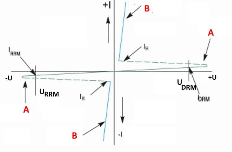
Designation:
- A – closed state.
- B – open state.
- U DRM (U PR) – maximum permissible voltage level for direct connection.
- U RRM (U OB) – maximum reverse voltage level.
- I DRM (I PR) – permissible direct current level
- I RRM (I OB) – permissible level of reverse switching current.
- I N (I UD) – holding current values.
Peculiarities
To have a complete understanding of symmetrical thyristors, it is necessary to talk about their strengths and weaknesses. The first include the following factors:
- relatively low cost of devices;
- long service life;
- lack of mechanics (that is, moving contacts that are sources of interference).
The disadvantages of the devices include the following features:
- The need for heat removal is approximately at the rate of 1-1.5 W per 1 A, for example, at a current of 15 A, the power dissipation value will be about 10-22 W, which will require an appropriate radiator. For ease of fastening to it for powerful devices, one of the terminals has a thread for a nut.

- Devices are subject to transients, noise and interference;
- High switching frequencies are not supported.
The last two points require a little clarification. In the case of high switching speed, there is a high probability of spontaneous activation of the device. Interference in the form of a voltage surge can also lead to this result. To protect against interference, it is recommended to bypass the device with an RC circuit.

In addition, it is recommended to minimize the length of the wires leading to the controlled output, or alternatively use shielded conductors. It is also practiced to install a shunt resistor between the T1 terminal (TE1 or A1) and the control electrode.
Application
This type of semiconductor elements was originally intended for use in the manufacturing sector, for example, to control electric motors of machine tools or other devices where continuously variable current control is required. Subsequently, when the technical base made it possible to significantly reduce the size of semiconductors, the scope of application of symmetrical thyristors expanded significantly. Today, these devices are used not only in industrial equipment, but also in many household appliances, for example:
- chargers for car batteries;
- household compressor equipment;
- various types of electric heating devices, ranging from electric ovens to microwaves;
- hand-held electric tools (screwdriver, hammer drill, etc.).
And this is not a complete list.
At one time, simple electronic devices were popular that allowed smooth adjustment of lighting levels. Unfortunately, dimmers based on symmetrical thyristors cannot control energy-saving and LED lamps, so these devices are not relevant now.
How to check the functionality of a triac?
You can find several methods online that describe the testing process using a multimeter; those who described them, apparently, have not tried any of the options themselves. In order not to be misleading, you should immediately note that testing with a multimeter will not be possible, since there is not enough current to open the symmetrical SCR. Therefore, we are left with two options:
- Use a pointer ohmmeter or tester (their current strength will be sufficient to trigger).
- Collect a special circuit.
Algorithm for checking with an ohmmeter:
- We connect the probes of the device to terminals T1 and T2 (A1 and A2).
- Set the multiplicity on the ohmmeter x1.
- We carry out a measurement, a positive result will be infinite resistance, otherwise the part is “broken” and can be gotten rid of.
- We continue testing, to do this we briefly connect pins T2 and G (control). The resistance should drop to about 20-80 ohms.
- Change the polarity and repeat the test from steps 3 to 4.
If during the test the result is the same as described in the algorithm, then with a high probability it can be stated that the device is operational.
Note that the part being tested does not have to be dismantled; it is enough to just turn off the control output (naturally, having first de-energized the equipment where the part that raises doubt is installed).
It should be noted that this method does not always allow reliable testing, with the exception of testing for “breakdown”, so let’s move on to the second option and propose two circuits for testing symmetrical thyristors.
We will not give a circuit with a light bulb and a battery in view of the fact that there are enough such circuits on the network. If you are interested in this option, you can look at it in the publication on testing thyristors. Let's give an example of a more effective device.

Designations:
- Resistor R1 – 51 Ohm.
- Capacitors C1 and C2 – 1000 µF x 16 V.
- Diodes - 1N4007 or equivalent, installation of a diode bridge, for example KTs405, is allowed.
- HL bulb – 12 V, 0.5 A.
You can use any transformer with two independent 12 Volt secondary windings.
Verification algorithm:
- Set the switches to their original position (corresponding to the diagram).
- We press SB1, the device under test opens, as indicated by the light bulb.
- Press SB2, the lamp goes out (the device is closed).
- We change the mode of the SA1 switch and repeat pressing SB1, the lamp should light up again.
- We switch SA2, press SB1, then change the position of SA2 again and press SB1 again. The indicator will turn on when the shutter hits minus.
Now let's look at another scheme, only universal, but also not particularly complicated.

Designations:
- Resistors: R1, R2 and R4 – 470 Ohm; R3 and R5 – 1 kOhm.
- Capacities: C1 and C2 – 100 µF x 10 V.
- Diodes: VD1, VD2, VD5 and VD6 – 2N4148; VD2 and VD3 – AL307.
A 9V battery, Krona type, is used as a power source.
Testing of SCRs is carried out as follows:
- Switch S3 is moved to the position as shown in the diagram (see Fig. 6).
- Briefly press button S2, the element under test will open, which will be signaled by the VD LED
- We change the polarity by setting switch S3 to the middle position (the power is turned off and the LED goes out), then to the bottom.
- Briefly press S2, the LEDs should not light up.
If the result corresponds to the above, then everything is in order with the tested element.
Now let's look at how to check symmetrical thyristors using the assembled circuit:
- We carry out steps 1-4.
- Press the S1 button - the VD LED lights up
That is, when you press the S1 or S2 buttons, the VD1 or VD4 LEDs will light up, depending on the set polarity (the position of the S3 switch).
Soldering iron power control circuit
In conclusion, we present a simple circuit that allows you to control the power of the soldering iron.

Designations:
- Resistors: R1 – 100 Ohm, R2 – 3.3 kOhm, R3 – 20 kOhm, R4 – 1 Mohm.
- Capacitances: C1 – 0.1 µF x 400V, C2 and C3 – 0.05 µF.
- Symmetrical thyristor BTA41-600.
The above diagram is so simple that it does not require configuration.
Now let's look at a more elegant option for controlling the power of a soldering iron.

Designations:
- Resistors: R1 – 680 Ohm, R2 – 1.4 kOhm, R3 – 1.2 kOhm, R4 and R5 – 20 kOhm (dual variable resistance).
- Capacitances: C1 and C2 – 1 µF x 16 V.
- Symmetrical thyristor: VS1 – VT136.
- DA1 phase regulator microcircuit – KP1182 PM1.
Setting up the circuit comes down to selecting the following resistances:
- R2 – with its help we set the minimum temperature of the soldering iron required for operation.
- R3 – resistor value allows you to set the temperature of the soldering iron when it is on the stand (switch SA1 is activated),
Figure 1 – general initial view
On the right side of the top plastic cover there was a hole for the handle of the built-in power regulator, which was not there. By luck, some time later I came across a working copy of the same fireplace. At first glance, the regulator was a rather complex circuit with two thyristors and many very powerful resistors. It made no sense to repeat it, although I have access to almost any Soviet radio components, since it would cost many times more than the version that is manufactured now.
To begin with, the fireplace was connected directly to the network, the current consumption turned out to be 5.6 A, which corresponds to the nameplate power of the fireplace 1.25 kW. But why waste so much energy, especially since it is not cheap, and you don’t always need to turn on the heater at full power. Therefore, it was decided to start searching for a powerful power regulator. In my stash I found a ready-made circuit from a Chinese vacuum cleaner, using a triac VTA12-600. The triac, with its rated current of 12 A, suited me perfectly. This regulator was a phase regulator, i.e. This type of regulator does not pass the entire half-wave of the mains sinusoidal voltage, but only part of it, thereby limiting the power supplied to the load. Is the adjustment carried out by opening the triac at the desired phase angle?

Figure 2 – a) usual form of mains voltage; b) voltage supplied through the regulator
Advantages of a phase regulator
:
- ease of manufacture
- cheapness
- easy handling
Flaws
:
With a simple circuit, normal operation is observed only with loads such as incandescent lamps
- with a powerful active load, an unpleasant hum (battering) appears, which can occur both in the triac itself and at the load (heating coil)
- creates a lot of radio interference
- pollutes the power grid
As a result, after testing the regulator circuit from a vacuum cleaner, rattling of the electric fireplace spiral was detected.

Figure 3 – View inside the fireplace
The spiral looks like a wound wire (I can’t determine the material) on two strips, filled with some kind of heat-resistant hardener to fix it on the edges of the strips. Perhaps the rattling could cause its destruction. Attempts were made to connect the choke in series with the load and to bypass the triac with an RC circuit (which is a partial solution to interference). But none of these measures gave complete relief from noise.
It was decided to use a different type of controller - discrete. Such regulators open the triac for a period of a whole half-wave of voltage, but the number of half-waves passed is limited. For example, in Figure 3, the solid part of the graph is the half-waves that passed through the triac, the dotted part is the half-waves that did not pass through, that is, at that time the triac was closed.

Figure 4 – Principle of discrete regulation
Advantages of discrete controllers
:
- less heating of the triac
- lack of sound effects even with a fairly powerful load
- no radio interference
- no pollution of the electrical network
Flaws
:
Voltage surges are possible (at 220V by 4-6 V with a load of 1.25 kW), which can be noticeable on incandescent lamps. This effect is not noticeable on other home appliances.
The identified drawback is more noticeable the lower the adjustment limit is set to. At maximum load there are absolutely no surges. As a possible solution to this problem, it is possible to use a voltage stabilizer for incandescent lamps. The following scheme was found on the Internet, which attracted attention with its simplicity and ease of control.

Figure 5 – Schematic diagram of a discrete controller
Description of control
When turned on for the first time, the indicator lights up 0. Turning on and off occurs by simultaneously pressing and holding two buttons. Adjustment more/less – each button separately. If you do not press any of the buttons, then after the last press, after 2 hours the regulator will turn off itself, the indicator will blink at the last operating load level. When disconnected from the network, the last level is remembered and will be set the next time it is turned on. Adjustment occurs from 0 to 9 and then from A to F. That is, a total of 16 adjustment steps. 
When making a board I used it for the first time LUT, and was not mirrored correctly when printing, so the controller is turned upside down. The indicator also did not match, so I soldered it with wires. When I was drawing the board, I mistakenly placed the zener diode after the diode, so I had to solder it on the other side of the board.

Recently, resistor and transistor power regulators have experienced a real renaissance. They are the most uneconomical. You can increase the efficiency of the regulator in the same way as the regulator by turning on a diode (see figure). In this case, a more convenient control limit is achieved (50-100%). Semiconductor devices can be placed on one heatsink. Yu.I.Borodaty, Ivano-Frankivsk region. Literature 1. Danilchuk A.A. Regulator power for soldering iron //Radioamator-Electric. -2000. -No. 9. -P.23. 2.Rishtun A Regulator tension on six parts //Radioamator-Electric. -2000. -No. 11. -P.15....
The load of this simple regulator can include incandescent lamps, heating devices of various types, etc., depending on the thyristors used. The method for setting up the regulator is contained in the selection of a variable control resistor. However, it is best to choose such a potentiometer in series with a constant resistor so that the voltage at the output of the regulator varies within the widest possible range. A. ANDRIENKO, Kostroma....
For the "Simple power regulator" circuit
The inductive load in the regulator circuit places strict demands on the triac management circuits - the synchronization of the management system must be carried out directly from the supply network; the signal must have a duration equal to the triac conduction interval. The figure shows a diagram of a regulator that meets these requirements, which uses a combination of a dinistor and a triac. The time constant (R4 + R5)C3 determines the delay angle of the unlocking of the dinistor VS1 and therefore the triac VS2. By moving the slider of the variable resistor R5, the power consumed by the load is regulated. Capacitor C2 and resistor R2 are used to synchronize and ensure the duration of the management signal. Capacitor S3 is recharged from C2 after switching since at the end of each half-cycle it receives a voltage of reverse polarity. To protect against interference generated by the regulator, two Filters R1C1 are introduced - in the power circuit and R7C4 - in the load circuit. To set up the device, you need to set resistor R5 to the position of maximum resistance and resistor R3 to set the minimum power on the load Capacitors C1 and C4 type K40P-2B for 400 V, capacitors C2 and SZ type K73-17 for 250 V Diode bridge VD1 can be replaced with diodes KD105B Switch SA1 designed for a current of at least 5 A. V.F. Yakovlev, Shostka, Sumy region. ...
For the circuit "POWER REGULATOR WITH FEEDBACK"
For the "144 MHz power amplifier" circuit
For the circuit "Triac power regulator"
The proposed device (Fig. 1) is a phase power device capable of operating with loads from several watts to several kilowatts. This design is a redesign of a previously developed device. The use of a different element base made it possible to simplify the power unit of the design, increase reliability and improve the operational characteristics of the regulator. As in the prototype, this regulator has a smooth and stepwise adjustment of the power supplied to the load. In addition, at any time (without touching the regulator knobs), the device can be switched to an operating mode when almost 100% of the power is supplied to the load. There is virtually no radio interference. The power switch is built on the powerful VS2. The minimum power of the connected load can be from 3 to 10 W. the maximum (1.5 kW) is limited by the type of triac used, its cooling conditions and the design of the noise suppression chokes. Welder regulator for to125-12 On low-power VT3 transistors. VT4 is an analogue of a unijunction transistor, which reinforces short pulses that open the low-power high-voltage thyristor VS1. The power supplied to the load depends on the resistance of the variable resistor R6. The opened low-power thyristor, in turn, opens the powerful triac VS2. Through the opened triac, the supply voltage is supplied to the load. To have a chance, for example, it’s time to reduce the brightness of the lamp or the temperature of the soldering iron. and then return to the previous set value, a step power control unit is built on the DD1 chip. When you first press the SB1 button, the DD1.2 trigger switches, a large logical voltage level ("G" appears at output 1 of DD1.2), transistor VT2 opens and bypasses the circuit for limiting the amplitude of the mains voltage V...
For the circuit "Soldering iron power switch"
Brilliant - simple. Compared to a diode, a variable resistor is neither simpler nor more reliable. But a soldering iron with a diode is rather weak, and a resistor allows you to work without overheating or underheating. Where can I get a powerful variable resistor of suitable resistance? It’s easier to find a permanent one, and replace the switch used in the “classical” circuit with a three-position one (see figure). ...
For the circuit "200 W power amplifier based on TDA 7294"
AUDIO equipmentAmplifier power 200 W based on TDA 7294 IC TDA7294 is developed and manufactured by the SGS-THOMSON Microelectronics group of companies. This is one of the most successful UMZCH microcircuits, which not only has high output power (100 W) and high reliability, but also provides the highest quality sound (among ICs). When creating powerful UMZCHs on bipolar transistors (and ICs), there is a danger of secondary breakdown, leading to their failure. Existing protection systems (SOA) when operating on a reactive load (real AC) lose their effectiveness. To circumvent these problems, powerful field-effect transistors are used at the output of the TDA7294, in which there is no secondary breakdown, and voltage amplification is performed by both bipolar and field-effect transistors. Combined bipolar -field technology with high-voltage powerful MOS transistors received the brand name BCD 100. at 144 MHz Yu.Grebnev (RA9AA) The case is made of fiberglass 2 mm thick, to which a radiator is attached along the entire perimeter. A hole is made in the bottom of the case exactly to the size of the transistor case, which sits on the radiator, and the bottom base is made of such thickness that the emitter terminals of the transistor lie on the foil of the case and are pressed against it with brass plates and M3 screws. To prevent the base and collector from touching the “ground,” the foil underneath the transistor body is removed by 3 mm, and the terminals are slightly bent upward. C2 and C3 are mounted vertically on G-stands made of brass, which ground the rotors, C1 and C4 - on P -shaped racks made of textolite. Amplifier design Details: C1, C2, C3, C4 - 1KPVM 1 (3...27pf). L1 - 3 turns with 0.8 mm wire, winding diameter 6 mm. L2 - 8 turns with 0.8 wire mm, winding diameter 5 mm, l=18mm.L3 - 4 turns with a 2x0.7 mm bus, winding diameter 8 mm, l=16mm.L4 - 4 turns with 0.8 mm wire, winding diameter 15 mm (resistor R2 inside the coil) .Transistor KT930A (30V, 2.4A), KT931A (30V, 3A). When using transistor KT931A, 2 turns are short-circuited at L2, three capacitors are added to the circuit, shown in dotted lines. By selecting these containers and L2, we achieve agreement between PA....
A significant disadvantage of thyristors is that they are half-wave elements; accordingly, in alternating current circuits they operate at half power. You can get rid of this drawback by using a back-to-back circuit for connecting two devices of the same type or by installing a triac. Let's figure out what this semiconductor element is, the principle of its operation, features, as well as the scope of application and testing methods.
What is a triac?
This is one of the types of thyristors, which differs from the basic type in a large number of p-n junctions, and as a consequence of this, in the principle of operation (it will be described below). It is characteristic that in the element base of some countries this type is considered an independent semiconductor device. This minor confusion arose due to the registration of two patents for the same invention.
Description of the operating principle and device
The main difference between these elements and thyristors is the bidirectional conductivity of electric current. Essentially, these are two SCRs with common control, connected back-to-back (see A in Fig. 1).
Rice. 1. Circuit with two thyristors, as an equivalent of a triac, and its conventional graphic designationThis gave the name to the semiconductor device, as a derivative of the phrase “symmetrical thyristors” and was reflected in its UGO. Let us pay attention to the designations of the terminals, since current can be carried in both directions, the designation of the power terminals as Anode and Cathode does not make sense, therefore they are usually designated as “T1” and “T2” (options TE1 and TE2 or A1 and A2 are possible). The control electrode is usually designated “G” (from the English gate).
Now consider the structure of the semiconductor (see Fig. 2.) As can be seen from the diagram, there are five junctions in the device, which allows you to organize two structures: p1-n2-p2-n3 and p2-n2-p1-n1, which, in fact, are two counter-current thyristors connected in parallel.
Rice. 2. Block diagram of a triac When negative polarity is formed at the power terminal T1, the trinistor effect begins to manifest itself in p2-n2-p1-n1, and when it changes, p1-n2-p2-n3.
Concluding the section on the principle of operation, we present the current-voltage characteristics and the main characteristics of the device.
Designation:
- A – closed state.
- B – open state.
- U DRM (U PR) – maximum permissible voltage level for direct connection.
- U RRM (U OB) – maximum reverse voltage level.
- I DRM (I PR) – permissible direct current level
- I RRM (I OB) – permissible level of reverse switching current.
- I N (I UD) – holding current values.
Peculiarities
To have a complete understanding of symmetrical thyristors, it is necessary to talk about their strengths and weaknesses. The first include the following factors:
- relatively low cost of devices;
- long service life;
- lack of mechanics (that is, moving contacts that are sources of interference).
The disadvantages of the devices include the following features:
- The need for heat removal is approximately at the rate of 1-1.5 W per 1 A, for example, at a current of 15 A, the power dissipation value will be about 10-22 W, which will require an appropriate radiator. For ease of fastening to it for powerful devices, one of the terminals has a thread for a nut.
- Devices are subject to transients, noise and interference;
- High switching frequencies are not supported.
The last two points require a little clarification. In the case of high switching speed, there is a high probability of spontaneous activation of the device. Interference in the form of a voltage surge can also lead to this result. To protect against interference, it is recommended to bypass the device with an RC circuit.
In addition, it is recommended to minimize the length of the wires leading to the controlled output, or alternatively use shielded conductors. It is also practiced to install a shunt resistor between the T1 terminal (TE1 or A1) and the control electrode.
Application
This type of semiconductor elements was originally intended for use in the manufacturing sector, for example, to control electric motors of machine tools or other devices where continuously variable current control is required. Subsequently, when the technical base made it possible to significantly reduce the size of semiconductors, the scope of application of symmetrical thyristors expanded significantly. Today, these devices are used not only in industrial equipment, but also in many household appliances, for example:
- chargers for car batteries;
- household compressor equipment;
- various types of electric heating devices, ranging from electric ovens to microwaves;
- hand-held electric tools (screwdriver, hammer drill, etc.).
And this is not a complete list.
At one time, simple electronic devices were popular that allowed smooth adjustment of lighting levels. Unfortunately, dimmers based on symmetrical thyristors cannot control energy-saving and LED lamps, so these devices are not relevant now.
How to check the functionality of a triac?
You can find several methods online that describe the testing process using a multimeter; those who described them, apparently, have not tried any of the options themselves. In order not to be misleading, you should immediately note that testing with a multimeter will not be possible, since there is not enough current to open the symmetrical SCR. Therefore, we are left with two options:
- Use a pointer ohmmeter or tester (their current strength will be sufficient to trigger).
- Collect a special circuit.
Algorithm for checking with an ohmmeter:
- We connect the probes of the device to terminals T1 and T2 (A1 and A2).
- Set the multiplicity on the ohmmeter x1.
- We carry out a measurement, a positive result will be infinite resistance, otherwise the part is “broken” and can be gotten rid of.
- We continue testing, to do this we briefly connect pins T2 and G (control). The resistance should drop to about 20-80 ohms.
- Change the polarity and repeat the test from steps 3 to 4.
If during the test the result is the same as described in the algorithm, then with a high probability it can be stated that the device is operational.
Note that the part being tested does not have to be dismantled; it is enough to just turn off the control output (naturally, having first de-energized the equipment where the part that raises doubt is installed).
It should be noted that this method does not always allow reliable testing, with the exception of testing for “breakdown”, so let’s move on to the second option and propose two circuits for testing symmetrical thyristors.
We will not give a circuit with a light bulb and a battery in view of the fact that there are enough such circuits on the network. If you are interested in this option, you can look at it in the publication on testing thyristors. Let's give an example of a more effective device.
Designations:
- Resistor R1 – 51 Ohm.
- Capacitors C1 and C2 – 1000 µF x 16 V.
- Diodes - 1N4007 or equivalent, installation of a diode bridge, for example KTs405, is allowed.
- HL bulb – 12 V, 0.5 A.
You can use any transformer with two independent 12 Volt secondary windings.
Verification algorithm:
- Set the switches to their original position (corresponding to the diagram).
- We press SB1, the device under test opens, as indicated by the light bulb.
- Press SB2, the lamp goes out (the device is closed).
- We change the mode of the SA1 switch and repeat pressing SB1, the lamp should light up again.
- We switch SA2, press SB1, then change the position of SA2 again and press SB1 again. The indicator will turn on when the shutter hits minus.
Now let's look at another scheme, only universal, but also not particularly complicated.
Designations:
- Resistors: R1, R2 and R4 – 470 Ohm; R3 and R5 – 1 kOhm.
- Capacities: C1 and C2 – 100 µF x 10 V.
- Diodes: VD1, VD2, VD5 and VD6 – 2N4148; VD2 and VD3 – AL307.
A 9V battery, Krona type, is used as a power source.
Testing of SCRs is carried out as follows:
- Switch S3 is moved to the position as shown in the diagram (see Fig. 6).
- Briefly press button S2, the element under test will open, which will be signaled by the VD LED
- We change the polarity by setting switch S3 to the middle position (the power is turned off and the LED goes out), then to the bottom.
- Briefly press S2, the LEDs should not light up.
If the result corresponds to the above, then everything is in order with the tested element.
Now let's look at how to check symmetrical thyristors using the assembled circuit:
- We carry out steps 1-4.
- Press the S1 button - the VD LED lights up
That is, when you press the S1 or S2 buttons, the VD1 or VD4 LEDs will light up, depending on the set polarity (the position of the S3 switch).
Soldering iron power control circuit
In conclusion, we present a simple circuit that allows you to control the power of the soldering iron.
Designations:
- Resistors: R1 – 100 Ohm, R2 – 3.3 kOhm, R3 – 20 kOhm, R4 – 1 Mohm.
- Capacitances: C1 – 0.1 µF x 400V, C2 and C3 – 0.05 µF.
- Symmetrical thyristor BTA41-600.
The above diagram is so simple that it does not require configuration.
Now let's look at a more elegant option for controlling the power of a soldering iron.
Designations:
- Resistors: R1 – 680 Ohm, R2 – 1.4 kOhm, R3 – 1.2 kOhm, R4 and R5 – 20 kOhm (dual variable resistance).
- Capacitances: C1 and C2 – 1 µF x 16 V.
- Symmetrical thyristor: VS1 – VT136.
- DA1 phase regulator microcircuit – KP1182 PM1.
Setting up the circuit comes down to selecting the following resistances:
- R2 – with its help we set the minimum temperature of the soldering iron required for operation.
- R3 – resistor value allows you to set the temperature of the soldering iron when it is on the stand (switch SA1 is activated),